

Organic light-emitting device
a light-emitting device and organic compound technology, applied in the direction of discharge tube luminescent screen, discharge tube/lamp details, discharge tube luminescent composition, etc., can solve the problems of insufficient device emission efficiency and stability, and achieve long continuous driving life and high emission efficiency
- Summary
- Abstract
- Description
- Claims
- Application Information
AI Technical Summary
Benefits of technology
Problems solved by technology
Method used
Image

Examples
example 1
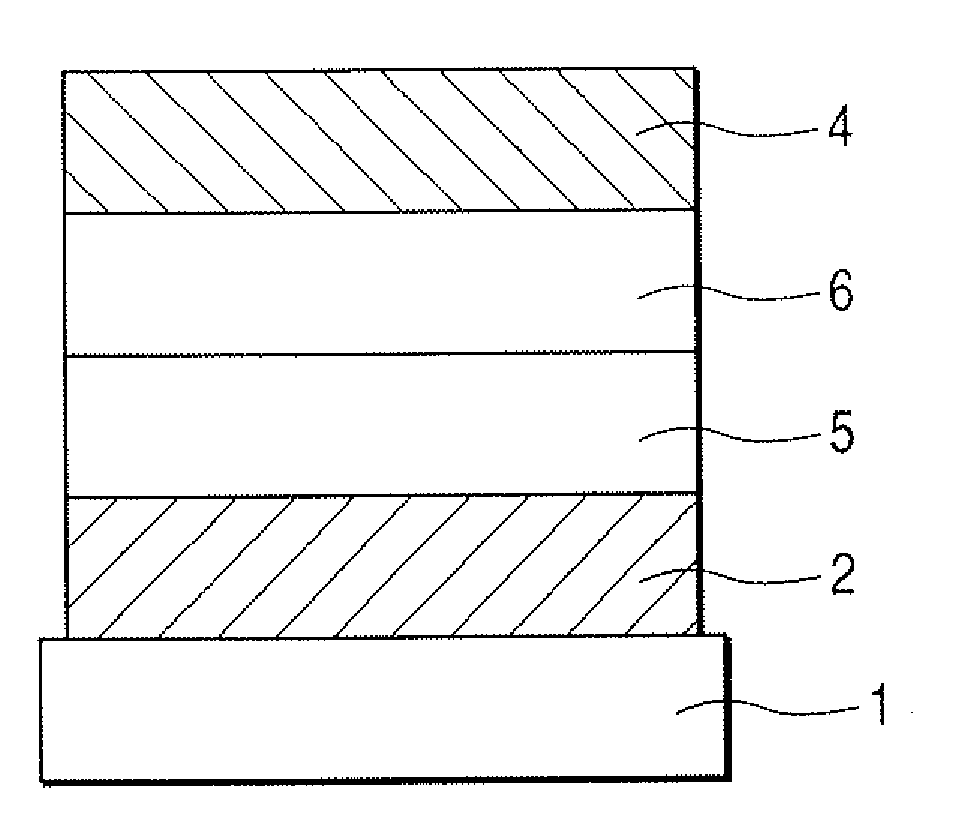
[0082]Indium tin oxide (ITO) was formed into a film having a thickness of 130 nm by a sputtering method to serve as an anode on a glass substrate as a substrate, and the resultant was used as a transparent, conductive supporting substrate. The resultant was subjected to ultrasonic cleaning in acetone and isopropyl alcohol (IPA) sequentially, and was then subjected to boiling cleaning in IPA, followed by drying. Further, the resultant was subjected to UV / ozone cleaning.
[0083]A chloroform solution was prepared by using Compound 1 shown below as a hole transport material in such a manner that the concentration of the compound would be 0.1 wt %.
[0084]The solution was dropped onto the above-mentioned ITO electrode, and the whole was subjected to spin coating initially at a number of revolutions of 500 RPM for 10 seconds and then at a number of revolutions of 1,000 RPM for 1 minute, whereby a film was formed. After that, the resultant was dried for 10 minutes in a vacuum oven at 80° C., w...
example 2
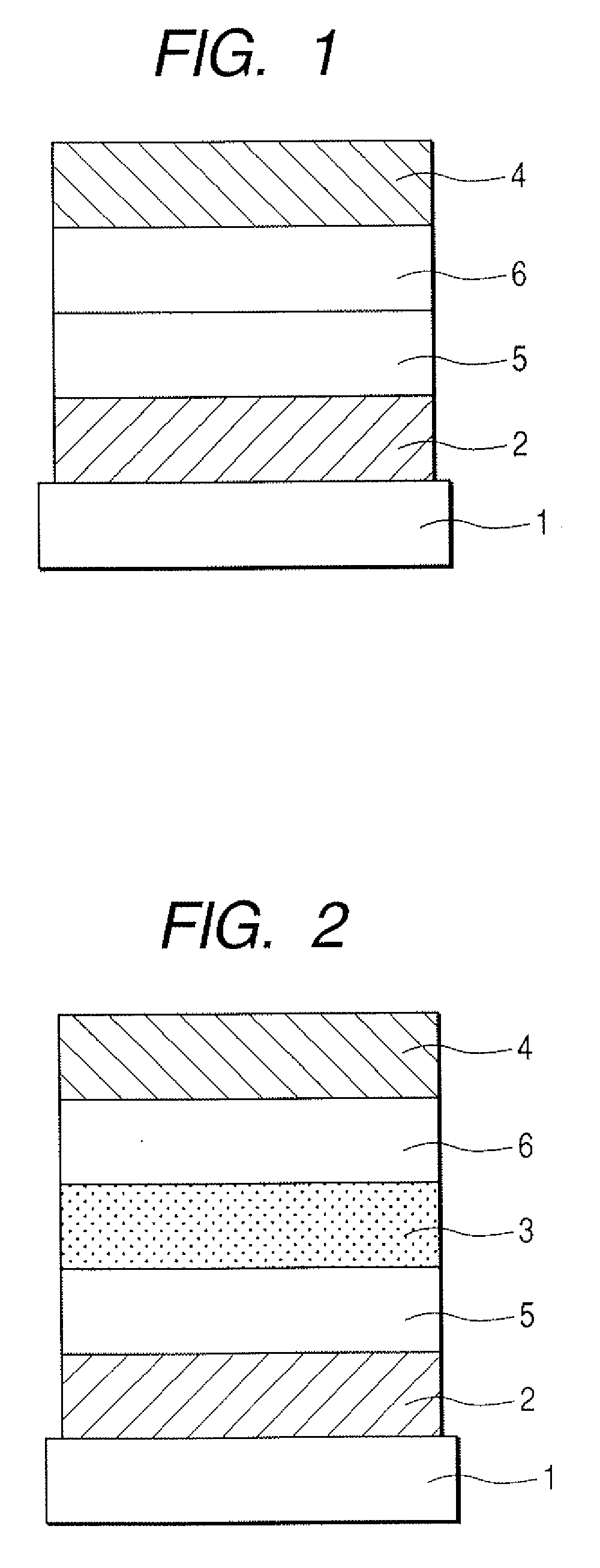
[0098]A light-emitting device was produced in the same manner as in Example 1 except that the host material of a light-emitting layer was constituted of Compound 4 shown below.
[0099]A voltage of 4.5 V was applied to the thus-obtained device while the ITO electrode (anode) was used as a positive electrode and the aluminum electrode (cathode) was used as a negative electrode. As a result, the device was observed to emit blue light derived from Compound 3 and having an emission luminance of 2,500 cd / m2, an emission efficiency of 5.5 lm / W, and a maximum emission wavelength of 460 nm.
[0100]Further, a voltage was applied to the device under a nitrogen atmosphere with a current density kept at 30 mA / cm2. As a result, a luminance half time was as long as about 1,400 hours.
[0101]The thin films of the host material and luminescent dopant of the light-emitting layer were each formed by vacuum deposition, and the HOMO energy of each of the thin films was measured with a photoelectron spectromet...
example 3
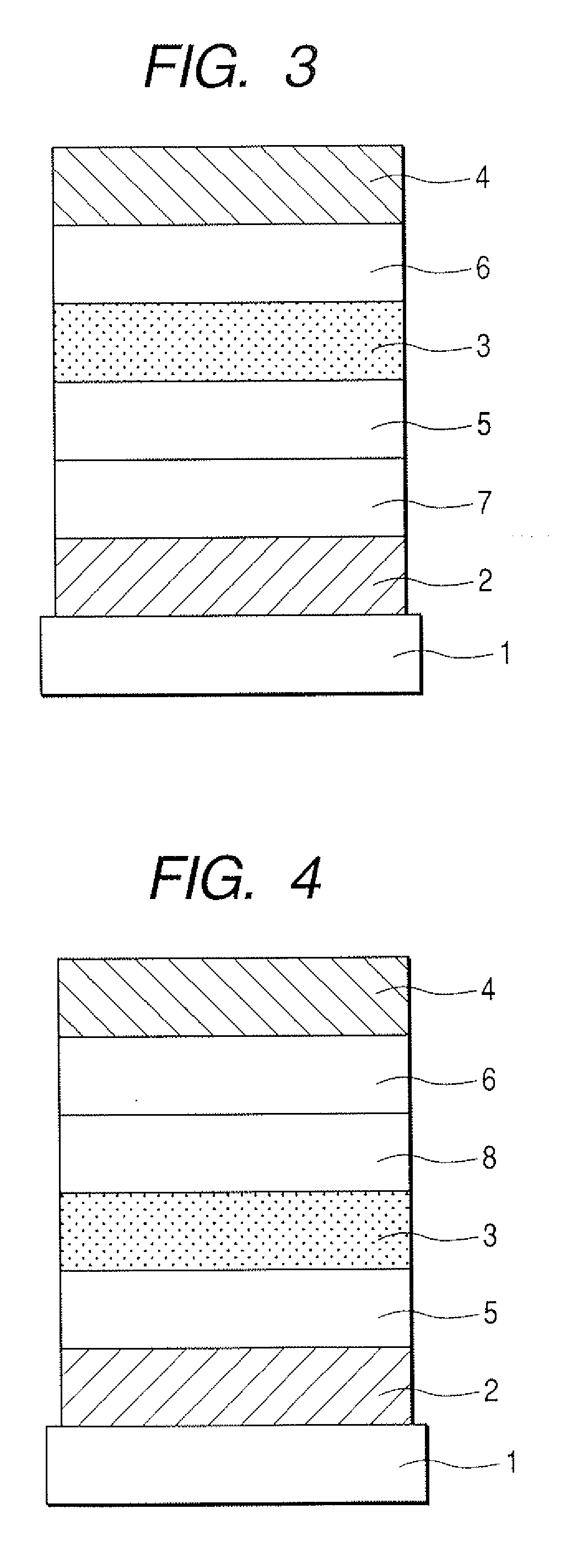
[0108]A light-emitting device was produced in the same manner as in Example 2 except that a material for an electron transport layer was changed to 2,9-bis[2-(9,9-dimethylfluorenyl)]phenanthroline.
[0109]A voltage of 4.5 V was applied to the device while the ITO electrode (anode) was used as a positive electrode and the aluminum electrode (cathode) was used as a negative electrode. As a result, the device was observed to emit blue light derived from Compound 3 and having an emission luminance of 2,400 cd / m2, an emission efficiency of 5.1 lm / W, and a maximum emission wavelength of 462 nm.
[0110]Further, a voltage was applied to the device under a nitrogen atmosphere with a current density kept at 30 mA / cm2. As a result, a luminance half time was as long as about 1,600 hours.
[0111]The measured energy gap of the electron transport material was 3.08 eV, which was larger than 3.00 eV.
PUM
 Abstract
Description
Claims
Application Information