High Strength Joining System for Fiber Reinforced Composites

a fiber reinforced composite and high-heavy technology, applied in the direction of coatings, layered products, chemical instruments and processes, etc., can solve the problems of high cost, dubious reliability, and laborious processes for increasing surface energy and availability of potential bond sites, so as to achieve high-heavy connections and enhance the integrity of the combined structure. the effect of reliable transfer

Inactive Publication Date: 2009-03-12
OBERMEYER HENRY K
View PDF99 Cites 14 Cited by
  • Summary
  • Abstract
  • Description
  • Claims
  • Application Information

AI Technical Summary

Benefits of technology

[0012]It is an object of one aspect of this invention to provide high strength connections between various fiber-reinforced structural components. For example, the interior of an aircraft fuselage structure might be provided with a generally circular zone of exposed fibers for the purpose of being adhesively bonded to a pressure bulkhead with its fuselage-fitting perimeter featuring similarly exposed fibers. Upon bonding, fibers continuous from within the fuselage structure are commingled and co-embedded in cured adhesive with fibers continuous from within the pressure bulkhead structure. The integrity of the combined structure is thus enhanced by continuity of fiber across the adhesive-to-cured-resin interfaces and thus does not rely on the strength of the adhesive-to-cured-resin bonds and also does not rely on the strength of un-reinforced adhesive. Loads may be reliably transferred from fiber to resin to fiber without the requirement for tensile load transfer across adhesive bond lines. Stresses within the adhesive itself are also reduced in accordance with the degree of fiber overlap achieved within the adhesive. Fiber overlap may be tailored to load requirements. For example, opposing electro-statically flocked bonding strips might be used in order to maximize the proportion of Z-axis fiber alignment within the joint. Connections with predominately shear loads might be adequately provided with partial exposure of woven reinforcing fabrics. Knitted fabrics would be expected to provide joint properties intermediate to those provided by flocked bonding strips and square woven fabric.
[0014]It is an object of a further aspect of this invention to provide a high strength, yet flexible, connection between several structural components. For example, the bonding of two relatively stiff structures which may move relative to each other may require a flexible joint in order to reduce joint loads to within safe limits. A landing gear or engine attachment to a fuselage might fall into this category. Provision, in accordance with this invention, of exposed fiber at the surfaces of the parts to be connected allows the creation of an elastomeric joint between otherwise relatively rigid structures. Integration of the exposed fibers of each structure into such an elastomeric joint provides not only joint attachment reliability but also the possibility of carrying substantial tensile loads through such a joint. Elastomeric connections of prior art have primarily used elastomeric elements in compression. In cases where loads reverse direction, redundant elastomeric elements have been required, with only one or the other elastomeric element carrying a load at any one time.
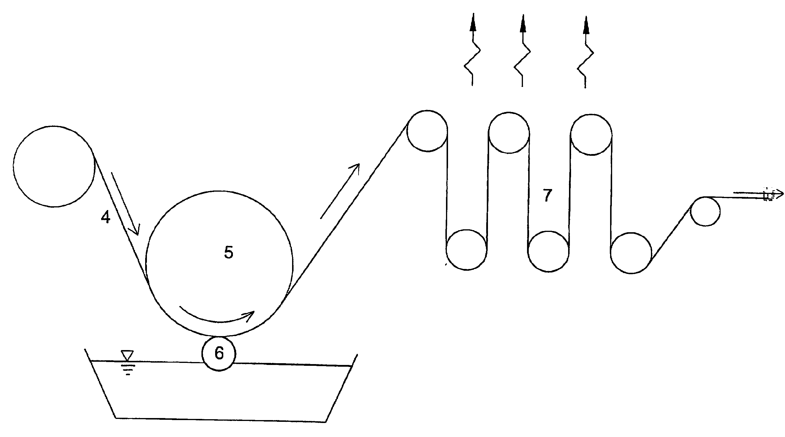
[0018]According to one aspect of an embodiment of the present invention, a zone of thermal gradient may be established normal to a desired boundary between resin impregnated fiber and non-resin impregnated fiber. A molten resin blocking substance such as paraffin may be supplied to the reinforcing fibers near the higher temperature end of the thermal gradient zone. The resin blocking substance, such as paraffin, will wet the heated fibers and follow the fibers by capillary action to a boundary where the temperature of the fiber causes solidification of the paraffin and cessation of capillary transport. Subsequent resin infusion of the portion of fiber not infused with paraffin results in a distinct resin boundary within the fiber matrix. Curing of the resin may be carried out at temperatures below the melting point of the resin blocking substance such as paraffin. After the resin is cured, the paraffin may be removed by vacuum sublimation followed by solution in citric acid solution, for example. This sequence leaves exposed non-resin infused fibers which may be readily incorporated into a secondary joint. For example, the marginal edges of two adjoining parts may be joined by overlapping or otherwise interlocking the exposed fibers of each part followed by resin infusion of the zone of interlocked fibers. The resulting structure benefits from continuity of reinforcement through the joint.
[0021]According to a further aspect of this invention a soluble flexible sheet may anchor short lengths of fiber oriented primarily normal to the plane of the elastomeric sheet. Such a sheet may be applied to the surface of an uncured composite structure and left in place during curing. Subsequent to curing, the flexible sheet may be dissolved, leaving exposed fibers protruding from the surface of the cured composite structure.
[0029]In accordance with one aspect of a further embodiment of this invention, a joint may be provided in which one or more components are match molded to each other. For example, a laminate or sandwich structure may be built to include one or more surface zones wherein the outer fibers are protected by a resin blocking substance. Either before or after curing of such a structure, additional structures may be built thereon which incorporate corresponding zones of resin blocked fiber in a back-to-back configuration with resin blocked fiber elements of the first structure. Upon curing of such assembled structures in their respective assembled positions, the structures may be disassembled from each other and their respective bonding zones cleaned of resin blocking substance. Such disassembly may be useful or required for the removal of mandrels or the insertion of other components, for example. After removal of resin blocking substance, the structures may subsequently be reassembled and adhesively bonded to each other with an assured fit.
[0033]In accordance with a further embodiment of one aspect of the present invention, a thermal gradient may be used to control the extent of infusion of a thermoplastic into a fiber matrix. Subsequent infusion of thermoset resin into the remainder of the fiber matrix can then be used to yield a part which may be thermally bonded to another such part with continuity of fiber reinforcement across the resin interfaces. This method combines the high glass transition temperature and favorable structural properties of thermoset resins with the weldability of thermoplastic parts.

Problems solved by technology

Polymer joints lacking fiber reinforcement can be expected to lack the inherent fatigue resistance of fiber reinforced structures.
Additionally, adhesively bonded joints between polymer structures are subject to environmental degradation.
The various processes for increasing the surface energy and availability of potential bond sites are labor intensive, expensive, of dubious reliability, and are subject to reversal by brief environmental exposure.
Although such structures may provide superior Z axis delamination resistance within integrally cured components, such structures do not in themselves provide for increased adhesive joint strength.
Such systems result in the conflicting requirements for good wetting properties of the fibers to be left behind in the cured resin, and for good release properties of the fiber to be peeled away.
Obviously, this would not work well with a single type of fiber with a single type of surface treatment.
Furthermore, release agents that might be applied to the fibers to be peeled may be prone to migrate during cure onto the fibers to be embedded, thus diminishing the strength and reliability of any adhesive joint which such embedded fibers are intended to reinforce.

Method used


Image

  • High Strength Joining System for Fiber Reinforced Composites
  • High Strength Joining System for Fiber Reinforced Composites
  • High Strength Joining System for Fiber Reinforced Composites

Examples


Embodiment Construction

[0047]Referring to FIGS. 1 and 2, a braided glass fiber cord at an initial temperature of 20 deg C., has been momentarily dipped in molten paraffin so as to allow infusion (wicking) of the molten paraffin to an intended future resin boundary. The infusion extends to a boundary 2 at which the molten paraffin dropped in temperature sufficiently to begin solidification and ceases to infuse. A transient temperature gradient thus controlled the extent of paraffin infusion. The paraffin in this case was used as a resin blocking substance. The specimen shown in FIGS. 1 and 2 was subsequently cooled to solidify the paraffin, infused with epoxy resin which that was then allowed to cure, and then cleaned of paraffin by sublimation and solution. The infusion of epoxy resin (under effectively isothermal conditions) was precisely controlled by the paraffin infusion boundary 2 between glass fiber infused with subsequently cured epoxy resin 3 and non-infused glass fiber 1. Such an arrangement is u...


PUM

PropertyMeasurementUnit
lengthaaaaaaaaaa
lengthaaaaaaaaaa
lengthaaaaaaaaaa

Abstract

The invention relates to join fiber reinforced composite structures with continuity of fiber reinforcement across adhesive-to-substrate boundaries. Thermal gradient control of the extent of infusion of resins or resin blocking substances, during manufacture of components to be subsequently bonded, provides partially exposed reinforcing fibers which serve to reinforce a subsequently formed joint or boundary.

Description

[0001]This application claims the benefit of U.S. Provisional Application No. 60 / 606,231 filed Aug. 31, 2004 which is hereby incorporated by reference.BACKGROUND OF THE INVENTION[0002]1. Field of Invention[0003]The present invention relates to connection of fiber reinforced structures, in particular the provision of exposed non-resin infused fiber at edges or surfaces of fiber reinforced components, which fiber may be beneficially used to reinforce subsequently formed joints between or to such fiber reinforced components.[0004]2. Description of Related Art[0005]Most adhesively bonded joints in fiber reinforced composites lack any continuity of reinforcement, with the notable exception of Z-pin technology such as is disclosed in U.S. Pat. No. 6,821,368 B2 to Benson et al. Continuity of fiber reinforcement across joints is desirable because the fiber reinforcement is far stronger than the polymer matrix and is stronger yet compared to adhesively bonded joints within a polymer matrix. ...

Claims


Application Information

Patent Timeline
Patent Type & Authority Applications(United States)
IPC IPC(8): B05D5/10B05D3/02
CPCB29C35/0266B29C66/721B29C70/546Y10T156/10B05D1/32B32B37/14C08L29/04B29C66/81455B29C65/02B29C65/14B29C65/1406B29C65/483B29C65/4845B29C65/5028B29C66/71B29C66/7212B29C66/72141B29C66/72525B29C66/73755B29C66/73793B29C66/7392B29C66/7394B29K2307/04B29K2077/00B29K2309/08B29K2067/00B29K2063/00B29K2083/00B29K2061/04B29K2033/08B29K2027/06
Inventor OBERMEYER, HENRY K.GILBERT, ERIC N.BAKER, GRANT QUINN
Owner OBERMEYER HENRY K
Why Eureka
Try Eureka