Substrate heater for material deposition

a heater and substrate technology, applied in the field of coating deposition, can solve the problems of significant limitations on the choice and design of heaters, affecting coating properties, and inapplicability of transfer by convection in most film deposition conditions, and achieve the effect of wide dynamic range of operational parameters

Inactive Publication Date: 2009-03-26
NEOCERA
View PDF20 Cites 10 Cited by
  • Summary
  • Abstract
  • Description
  • Claims
  • Application Information

AI Technical Summary

Benefits of technology

[0018]It is therefore an object of the present invention to provide a “universal” substrate heater

Problems solved by technology

The pressure and nature of a gas in the process chamber also affects the coating properties.
These conditions set significant limitations on the choice and design of a heater for heating the substrate up to the required temperature during each process step.
Transfer by convection is not applicable in most film deposition conditions, since density of particles in the chamber atmosphere is too small at a low pressure (<10 Torr) or vacuum conditions.
Often mechanical clamping does not produce good thermal contact, and then a soft, conformal to the heater and wafer surface material is used to fill the gap therebetween.
This approach has a limited applicability however due to the facts that: (a) silver starts evaporating at temperature above ˜900° C., and contaminates the wafer surface; (b) wafers of a size greater than ˜20 mm may be damaged when removed from the heater after processing.
The filament, however, cannot be used in a low vacuum, or in an oxidizing ambient gas in chamber since Tungsten oxidizes quickly and loses it's electrical conductivity.
Further, the platinum wire heater cannot be used as a contact heater.
In addition, Platinum is prohibitively exp

Method used


Image

  • Substrate heater for material deposition
  • Substrate heater for material deposition
  • Substrate heater for material deposition

Examples


Embodiment Construction

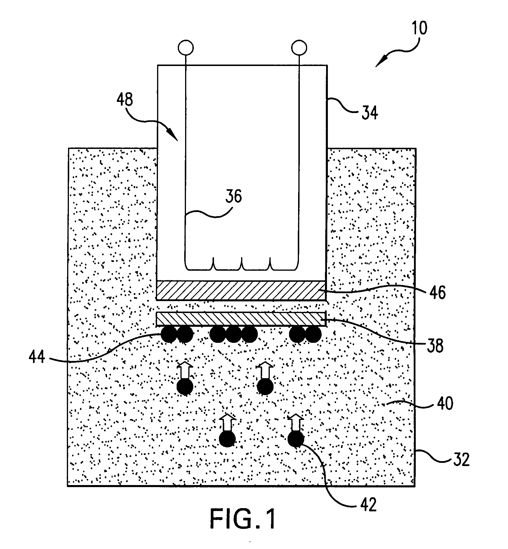
[0036]Referring to FIG. 1, illustrating the concept of the present substrate heater, a system 10 for material deposition includes a process chamber 32 and a heater chamber 34 separated each from the other by a high-temperature and oxidation resistant material which is tolerant to vacuum conditions. The heater chamber 34 contains a heating filament 36 and is filled with a gas suitable for the heating filament or it may be open to air.

[0037]A substrate 38 is positioned in the process chamber 32 which is filled with a process gas 40. The condensable particles (atoms / ions) 42 in the process chamber 32 flow to the substrate 38 and condense on the surface thereof to form a deposited material 44. The heat from the filament 36 is transferred to the substrate 38 through a hot (radiating) surface 46 formed from a high-temperature and oxidation resistant material, such as, for example, Inconel. By using the radiating surface 46, a uniform heating of the substrate 38 to high process temperature...


PUM

PropertyMeasurementUnit
Lengthaaaaaaaaaa
Temperatureaaaaaaaaaa
Volumeaaaaaaaaaa

Abstract

A radiative heater for substrates in a physical vapor deposition process for fabricating films of materials in a wide dynamic range of process temperatures and gas pressures includes a heat radiating member made from a high-temperature and oxidation resistant material tolerant to vacuum conditions which separates a heater volume containing heating filaments from a process volume which contains a deposition substrate heated by radiation of the walls of the heat radiating member. The heating elements extend through the body of the heat radiating member as well as in proximity to its surface to provide delivery of the heat to the substrate. The heat radiating member is shaped to form a cavity containing the substrate. The walls of the cavity envelope the substrate and radiate heat towards the substrate. Alternatively, the substrate is adhered to the flat surface of the heat radiating member.

Description

FIELD OF THE INVENTION[0001]The present invention is directed to coating deposition; and in particular, to a substrate heater in a vapor deposition system.[0002]More in particular, the present invention is directed to a substrate heater capable of uniformly heating substrates over a wide range of temperatures and is capable of operating under limitations of a multi-step deposition process.BACKGROUND OF THE INVENTION[0003]In material deposition, specifically in coating deposition, a condensable material is provided in a process chamber which condenses onto a substrate so that the thickness of the coating increases with time. The condensable materials may be provided, at least in vicinity of the substrate surface, through variety of mechanisms. For example, a gas containing at least a fraction of the condensable matter, e.g., material's vapor, may serve as the condensation material source. The gas may also be supplied in a partially ionized (plasma) state. A condensable component may ...

Claims


Application Information

Patent Timeline
IPC IPC(8): C23C14/54A21B2/00
CPCC23C14/541
Inventor STRIKOVSKI, MIKHAILKOLAGANI, SOLOMONKIM, JEONGGOO
Owner NEOCERA
Why Eureka
Try Eureka