[0005]In various aspects, the present disclosure provides methods of reducing
pollution generated by a combustion source. The methods include reducing an initial amount of
sulfur oxides present in a fluid
stream exiting a combustion source by contacting the fluid stream with a
solid material formed by admixing a
slag component having one or more reactive
silicate compounds with a binder component. In various embodiments prior to contact with the
solid material, the fluid stream has a temperature of less than about 600° F. (about 316° C.). Removal efficiency of the sulfur oxides present in the fluid stream is preferably above 20% and in various embodiments is even higher, reaching greater than or equal to about 70%, as compared to the initial amount of sulfur oxides present in the fluid stream prior to contact.
[0006]Another aspect of the disclosure provides a method of reducing
pollution generated by a combustion source, comprising reducing an initial amount of
nitrogen oxides present in a fluid stream exiting a combustion source by contacting the fluid stream with a
solid material formed by admixing a slag component having one or more reactive
silicate compounds with a binder component. Prior to contact with the
solid material, the fluid stream has a temperature of less than about 600° F. (about 316° C.). The amount of
nitrogen oxides present in the fluid stream after contact with the solid material is reduced by a removal efficiency of greater than or equal to about 20%, as compared to the initial amount of
nitrogen oxides present in the fluid stream prior to contact.
[0007]Another embodiment of the present disclosure provides a method of reducing
pollution generated by a combustion source, comprising reducing an initial amount of
air pollutants comprising sulfur oxides,
nitrogen oxides, and
carbon dioxide, the
air pollutants present in a fluid stream exiting a combustion source, by contacting the fluid stream with a solid material formed by admixing a slag component having one or more reactive
silicate compounds with a binder component. In an exemplary embodiment, prior to contact with the solid material, the fluid stream has a temperature of less than about 600° F. (about 316° C.). The total amount of air pollutants present in the fluid stream after contact with the solid material is reduced by a removal efficiency of greater than or equal to about 20%, as compared to the initial total amount of air pollutants present in the fluid stream prior to contact.
[0008]In another aspect, the disclosure provides a pollution abatement
system comprising a combustion source that generates an effluent stream comprising at least one air
pollutant selected from the group consisting of: sulfur oxides, nitrogen oxides, carbon dioxide that is present in the effluent stream at an initial amount. The
system includes a
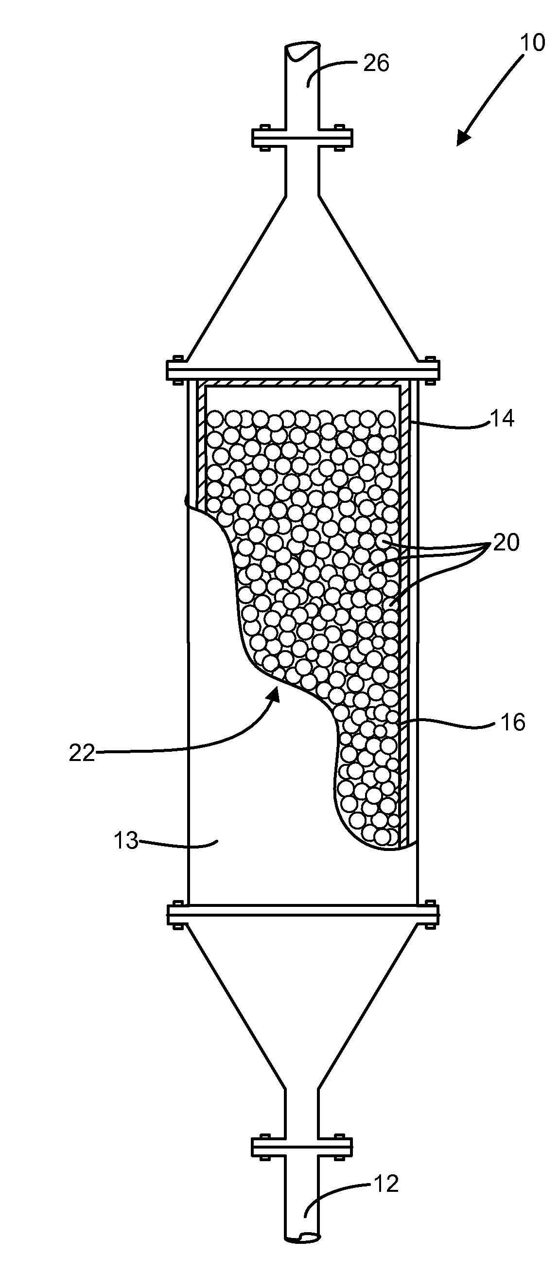
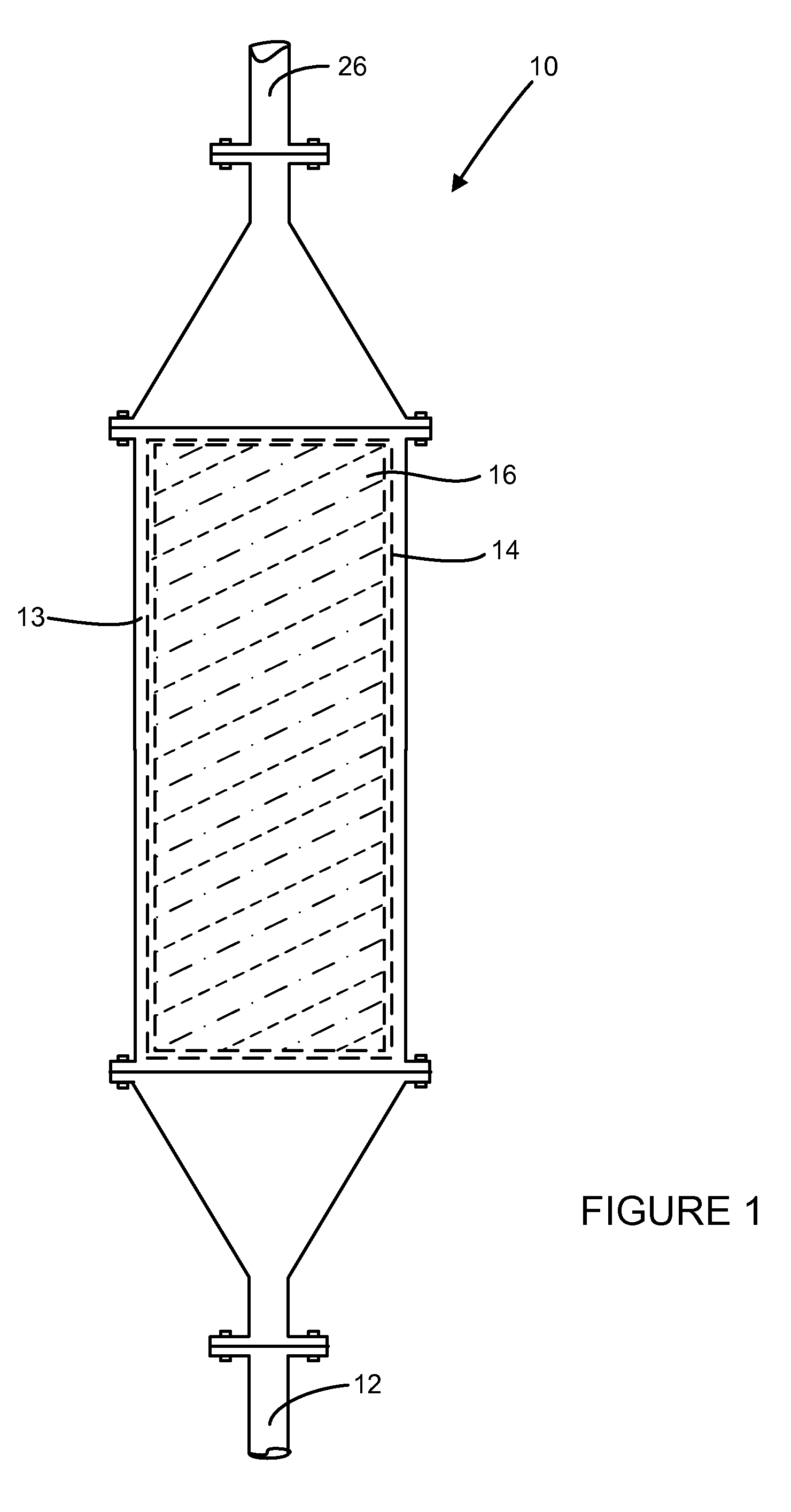
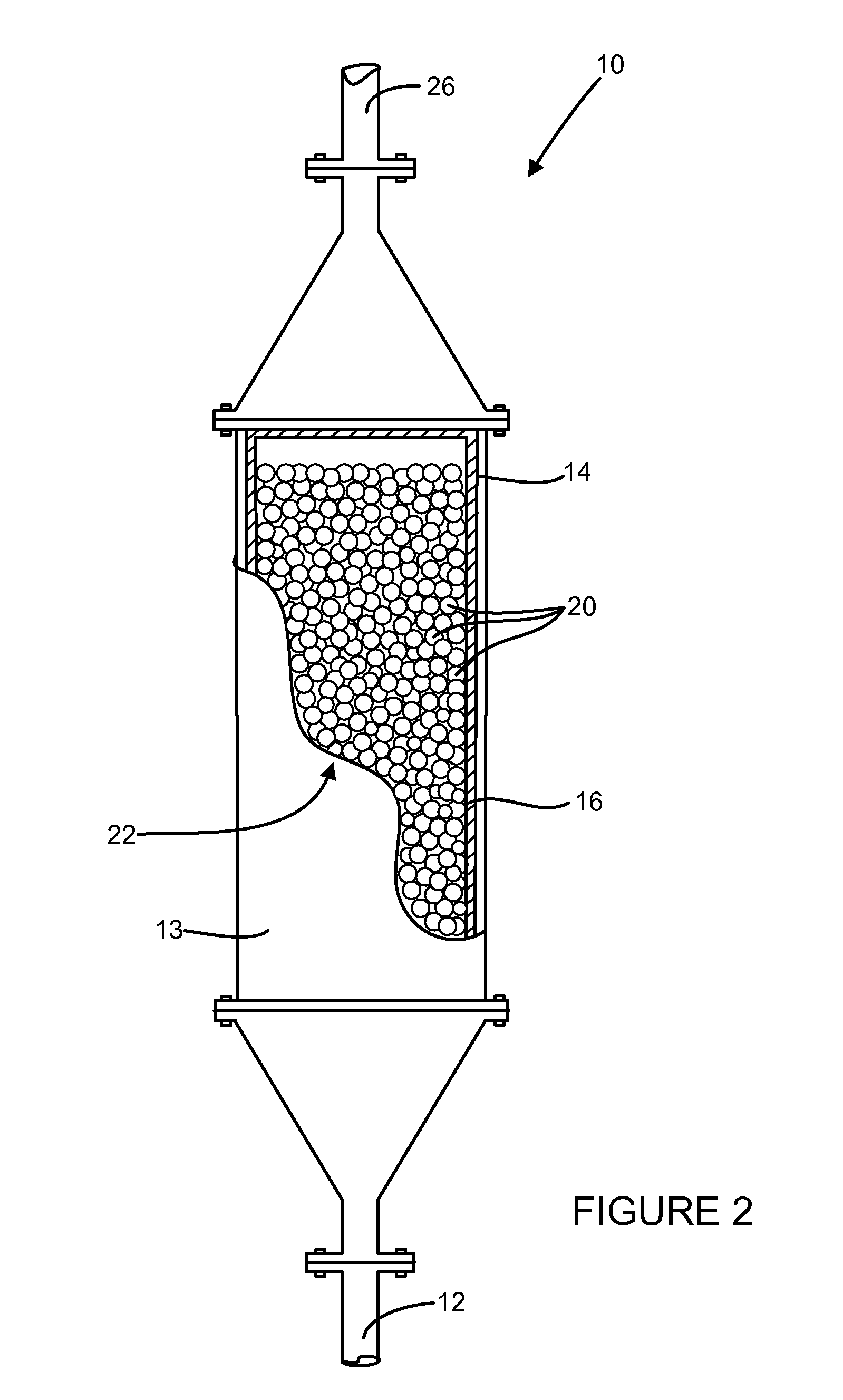
packed bed reactor having an inlet for receiving the effluent stream and an outlet. The reactor has at least one chamber comprising a plurality of solid particles having an average particle
diameter size of about 0.25 mm to about 12 mm, wherein the solid particles are formed by admixing a slag component having one or more reactive silicate compounds with a binder component. The chamber has a volume to provide a sufficient
residence time to reduce an amount of the air
pollutant by a removal efficiency of greater than or equal to about 20% in the effluent stream as compared to the initial amount.
[0009]In another aspect, the disclosure provides a method of reducing pollution generated by a combustion source, comprising introducing an effluent fluid stream generated in a combustion source to a
packed bed reactor, where the effluent stream has a temperature of less than about 600° F. (about 316° C.). The effluent fluid stream has an initial amount of at least one air
pollutant selected from the group consisting of: sulfur oxides, nitrogen oxides, and carbon dioxide, and the packed
bed reactor has at least one chamber comprising a plurality of solid particles having an average particle
diameter size of about 0.25 mm to about 12 mm that are formed by admixing a slag component having one or more reactive silicate compounds with a binder component. The reactor preferably operates with a removal efficiency of the air pollutant of greater than or equal to about 20%.
[0011]In various other aspects, the disclosure provides methods of reducing sulfur oxides, nitrogen oxides, and / or carbon dioxide emissions from effluent streams generated by stationary combustion sources (e.g., boilers, incinerators),
cement kilns,
lime kilns, iron furnaces and steel furnaces. In this manner, various aspects of the disclosure provide an effective means for removing sulfur oxides, nitrogen oxides, and / or carbon dioxide emissions, thus controlling
greenhouse gas emissions, while further recycling at least one industrial byproduct, and preferably multiple byproduct materials, to form a useful product.

