Metal pattern forming method

a metal pattern and forming method technology, applied in the direction of printed circuit manufacturing, liquid/solution decomposition chemical coating, coating, etc., can solve the problems of high cost, high cost, and high cost, and achieve high degree of accuracy, increase the thickness of the metal pattern, and increase the film thickness

Inactive Publication Date: 2009-04-02
FUJIFILM CORP
View PDF3 Cites 5 Cited by
  • Summary
  • Abstract
  • Description
  • Claims
  • Application Information

AI Technical Summary

Benefits of technology

[0016]In this aspect of the present invention, the two types of solutions, a metal salt solution and an acetylene compound solution are applied separately onto the substrate to form the metal precipitate on the substrate. Therefore, the two solutions are not mixed with each other before the application onto the substrate and hence a monomer of the metal salt does not form and even if an inkjet apparatus is used, it is possible to prevent blockages of the nozzles. Consequently, it is possible to achieve stable ejection of the solution.
[0017]Furthermore, since the second liquid (i.e., the other of the metal salt solution and the acetylene compound solution) is patterned on top of the thin layer of the first liquid (i.e., one of the metal salt solution and the acetylene compound solution), then the application object onto which the second liquid is to be applied is always the thin layer of the first liquid (even when the type of the substrate is changed). Consequently, patterning is possible regardless of the type of substrate, and a metal pattern can be formed in a stable fashion. Moreover, by depositing both of the two solutions by means of an inkjet apparatus, it is possible to reduce the amount of solution used, as well as achieving a uniform film thickness.
[0020]Moreover, when the acetylene compound and the metal salt react together, firstly, a metal acetylide π complex is formed. This metal acetylide π complex produces a vigorous reaction which generates heat, and therefore at the depositing points of the ejected ink droplets, the reduction reaction occurs rapidly to generate the metal precipitate (the metal acetylide is solidified), thus preventing undesirable spreading of the deposited droplets or interference between deposited droplets. Consequently, it is possible to improve the accuracy of the metal pattern.
[0022]In cases where the metal salt solution is applied as the first liquid (i.e., one of the metal salt solution and the acetylene compound solution), it is possible to dry the solvent of the metal salt solution and to precipitate the metal salt on the substrate by heating the substrate on which the metal salt solution has been applied. By then depositing an acetylene compound solution, it is possible to promote the formation of the metal precipitate on the substrate. Furthermore, by heating after depositing the first liquid and the second liquid, a portion of the acetylene compound is decomposed due to the heat and a reducing group is generated. Due to this effect, the silver is reduced to form the metal precipitate, and hence a metal pattern can be formed.
[0024]In this aspect of the present invention, it is possible to form a desirable metal pattern. Moreover, since processing can be carried out at a low temperature and in a short time compared to a method in the related art, then the method can also be applied to a substrate which has poor resistance to heat.
[0026]When forming a metal pattern by printing directly using an inkjet method, since the amount of deposited solution is small, then the film is formed to a very thin thickness of 1 μm or less. In the above aspect of the present invention, by carrying out a plating process after forming the metal precipitate on the substrate, it is possible to increase the thickness of the metal pattern readily. Furthermore, in order to increase the film thickness by means of a plating process, it is desirable that the metal salt solution should use a solution of a precious metal salt including an element belonging to one of group 8, group 9 and group 10 in the periodic table.

Problems solved by technology

However, photolithography involves various issues, such as the fact that costs are generally high because it takes a long time of one month or so to make a photo mask, the fact that a large volume of chemicals which are considered to present a considerable environmental burden are used, such as etching liquid, developer liquid, resist stripper, and the like, and the fact that all of the processes are redundant, and so on.
However, the method described in Japanese Patent Application Publication No. 2002-134878 uses a silver colloid dispersion and hence there are concerns with regard to the adhesiveness to the substrate.
Hence, there is a problem in that this method is difficult to apply to a substrate which has poor resistance to heat.
Moreover, catalytic activity is obtained in a relatively low temperature process without using palladium which is highly expensive, and the adhesive force with respect to the substrate is strong since a chemical change occurs in the heating step and the material reacts with the substrate.
However, if it is sought to print a metal pattern, such as a pattern for a plating catalyst or a conductive pattern for an electrical circuit, or the like, directly onto a substrate by depositing metal acetylide solution from the nozzle section of an inkjet apparatus as the depositing apparatus, then the following problems occur.
(1) If a σ complex is used as a silver salt monomer, then the monomer is precipitated by liquid evaporation and condensation in the nozzle section, and therefore nozzle blockages and ejection failures are liable to occur.
(2) If a π complex is used as a silver salt monomer, then since the π complex is thermally instable, it suffers severe decomposition upon assuming a solvent-free state, and therefore has not allowed stable use.
Furthermore, it has not been possible to eliminate general problems which are intrinsic to inkjet systems, namely, the problem of wetting and spreading of the deposited ink which prevents the formation of fine patterns, the mutual interference between deposited droplets and the consequent decline in patterning accuracy.

Method used


Image

  • Metal pattern forming method
  • Metal pattern forming method
  • Metal pattern forming method

Examples


Embodiment Construction

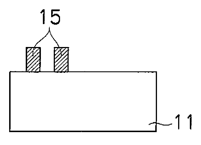
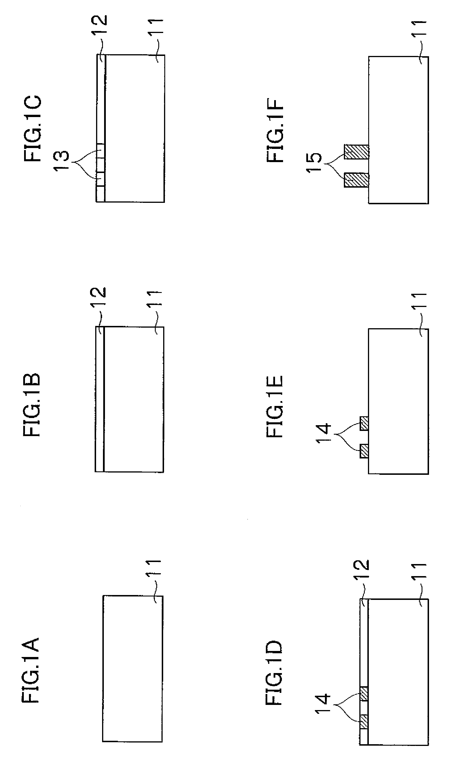
[0030]The method of forming a metal pattern according to an embodiment of the present invention forms a desired metal pattern by depositing two types of solution, namely, a metal salt solution and an acetylene compound, separately onto a substrate, thereby synthesizing a metal acetylide compound on the substrate and precipitating metal particles. In this case, at least one of the metal salt solution and the acetylene compound is deposited by means of an inkjet apparatus to print a metal pattern directly onto the substrate.

Metal Salt Solution

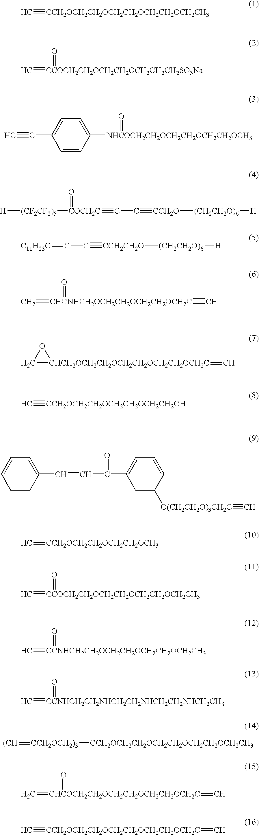
[0031]Firstly, the metal salt solution will be described. The metal in the metal salt solution according to the present embodiment is an element belonging to group 8, group 9, group 10 or group 11 of the periodic table. For example, nickel, ruthenium, rhodium, palladium, platinum, copper, silver, gold, or the like, can be used as the metal in the metal salt solution, and it is preferable to use silver or copper. Furthermore, it is also possible t...


PUM

PropertyMeasurementUnit
temperatureaaaaaaaaaa
volumeaaaaaaaaaa

Abstract

A metal pattern forming method includes the steps of: applying one of a metal salt solution and an acetylene compound solution onto the substrate, the acetylene compound solution containing an acetylene compound expressed by a general formula of:(R·(C≡C)l)k−(L)−(A)m,where R is one of a metal element, hydrogen, a carboxyl group or salt thereof, an alkyl group, a cycloalkyl group, an alkenyl group, an alkynyl group, an aryl group, an aralkyl group and a heterocyclic group, L is one of a compound linking A with a carbon-carbon triple bond and a group having (k+m) valency, A is one of a polyoxyether group, a polyaminoether group and polythioether group, k and l are integers not less than 1, and m is an integer not less than 0; and then applying the other of the metal salt solution and the acetylene compound solution onto the substrate so that the metal salt solution reacts with the acetylene compound solution to form a metal precipitate on the substrate, wherein at least one of the applying steps is performed by using an inkjet apparatus to directly form the metal pattern composed of the metal precipitate on the substrate.

Description

BACKGROUND OF THE INVENTION[0001]1. Field of the Invention[0002]The present invention relates to a metal pattern forming method, and in particular, a method for forming a metal pattern by depositing an acetylene compound and an ink liquid containing a metal salt onto a substrate, and synthesizing a metal acetylide on the substrate.[0003]2. Description of the Related Art[0004]In general, a photolithography method (also referred to simply as “photolitho”) has been used as a method of forming a metal pattern. In the photolithography method, a resist layer is formed of a dry film resist or liquid resist on a copper clad laminated plate constituted of an insulating layer and copper foil. This resist layer is then irradiated with ultraviolet light through a photomask, and then developed, thereby patterning the resist layer. Thereupon, a metal pattern is obtained by removing the copper foil which is not covered with the patterned resist layer, by means of etching with phosphoric acid, or t...

Claims


Application Information

Patent Timeline
Patent Type & Authority Applications(United States)
IPC IPC(8): B05D3/02
CPCC23C18/08H05K2203/122C23C18/1651C23C18/1653C23C18/1658C23C18/166C23C18/1692C23C18/31C23C18/32C23C18/38C23C18/42H05K3/105H05K2203/013H05K2203/1157C23C18/161
Inventor KAWATA, KENINOUE, SEIICHIMAEDA, YASUHIKO
Owner FUJIFILM CORP
Why Eureka
Try Eureka