A method of forming a thermal protective coating on a super alloy metal substrate

a technology of super alloy metal and protective coating, which is applied in the direction of chemical vapor deposition coating, blade accessories, machines/engines, etc., can solve the problems affecting adhesion, and achieve the effects of long-term resistance to spalling of ceramic layers, small thickness, and light weigh

Active Publication Date: 2009-04-02
SN DETUDE & DE CONSTR DE MOTEURS DAVIATION S N E C M A
View PDF16 Cites 3 Cited by
  • Summary
  • Abstract
  • Description
  • Claims
  • Application Information

AI Technical Summary

Benefits of technology

[0020]An object of the invention is to provide a gas turbine part comprising a superalloy metal substrate provided with a protective coating having a bonding under-layer between the substrate and the ceramic outer layer that is stable and that presents long-term resistance to spalling of the ceramic layer, while being small in thickness and therefore light in weight.

Problems solved by technology

it constitutes a diffusion barrier against certain elements of the metal substrate which would otherwise contaminate the film of alumina, and would consequently affect the interface between the bonding underlayer and the outer ceramic layer, thereby affecting the adhesion thereof.

Method used


Image

  • A method of forming a thermal protective coating on a super alloy metal substrate
  • A method of forming a thermal protective coating on a super alloy metal substrate
  • A method of forming a thermal protective coating on a super alloy metal substrate

Examples


example 1

[0092]Metal parts were used made of a single crystal superalloy based on nickel and having the following composition (percentages by weight): 6.5% Co, 7.5% Cr, 5.3% Al, 1.2% Ti, 8% Ta, 2% Mo, 5.5% W, with the balance being Ni.

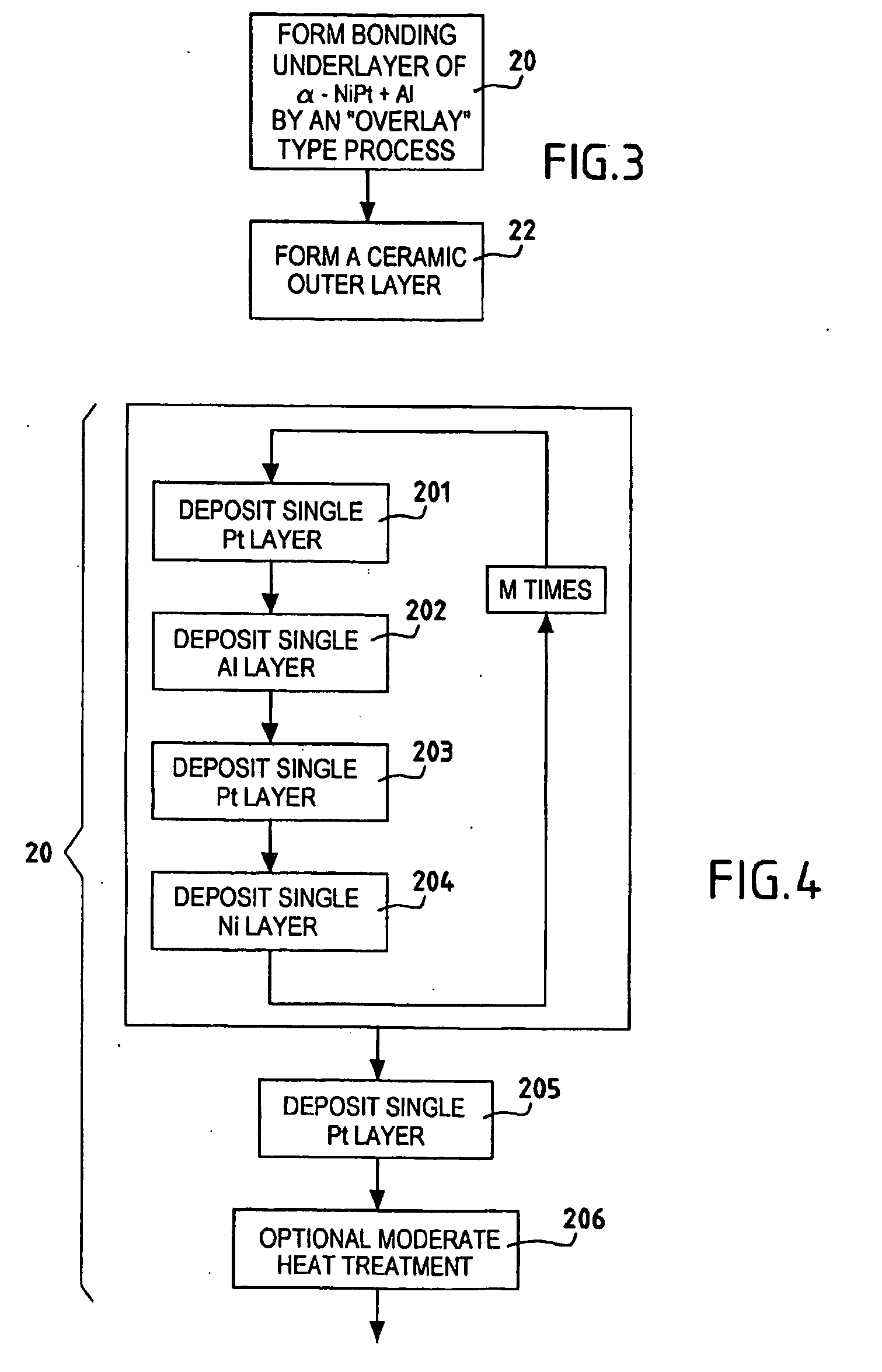
[0093]Parts were provided with alternating layers of platinum and aluminum by a physical vapor deposition process using cathode sputtering, in application of the second implementation described above (FIG. 7). 84 single layers of platinum were deposited each having a thickness of 30 nm, alternating with 83 single layers of aluminum each having a thickness of 66 nm.

[0094]Temperature was raised to 700° C. for 2 h in order to trigger an exothermal reaction between the single layers, causing a PtAl2 type platinum and aluminum intermetallic compound to be formed in a layer having a thickness of 7.5 μm.

[0095]Thereafter, a ceramic outer layer of zirconia ZrO2 stabilized with yttrium oxide Y2O3 (representing 8% by weight) was deposited. Deposition took place as describ...

example 2

[0096]The procedure was the same as in Example 1, but the number of single layers of platinum and aluminum was limited so as to obtain, after exothermal reaction between them, a PtAl2 type intermetallic compound in a layer having a thickness equal to about 2.5 μm.

[0097]The microphotograph of FIG. 8 shows the results that were obtained.

example 3

For Comparison

[0098]On substrates having the same composition as that of Examples 1 and 2, a bonding underlayer was formed by electro-deposition of a platinum layer and by vapor aluminization so as to obtain, in a manner that is known in the prior art, a bonding underlayer corresponding to a platinum-enriched P-type phase of the Ni—Al binary phase diagram. The thickness of the bonding underlayer was 60 μm. Thereafter, a ceramic outer layer was formed as described in Example 1.

[0099]Tests for ability to withstand thermal cycling in an oxidizing medium (air) were performed on the parts A, B, and C as obtained in Examples 1, 2, and 3 respectively, each cycle comprising a rapid temperature rise up to 1100° C. which was maintained for 1 h, after which there was a return to ambient temperature which was maintained for 15 minutes (min).

[0100]As shown in FIG. 9, the parts B withstood 624 cycles in satisfactory manner, which is a very remarkable result given the very small thickness (2.5 μm)...


PUM

PropertyMeasurementUnit
temperatureaaaaaaaaaa
thicknessaaaaaaaaaa
temperatureaaaaaaaaaa

Abstract

A method of forming a gas turbine part includes forming a bonding underlayer on a superalloy metal substrate, the underlayer including an intermetallic compound of aluminum, nickel, and platinum, and forming a ceramic outer layer on the alumina film formed on the bonding underlayer. The bonding underlayer essentially comprises an Ni—Pt—Al ternary system constituted by an aluminum-enriched α-NiPt type structure, in particular an Ni—Pt—Al ternary system having a composition NizPtyAlx in which z, y, and x are such that 0.05≦z≦0.40, 0.30≦y≦0.60, and 0.15≦x≦0.40.

Description

CROSS REFERENCE OF RELATED APPLICATION[0001]This application is a Divisional of patent application Ser. No. 10 / 974,973 filed Oct. 28, 2004, which is incorporated herein by reference.BACKGROUND OF INVENTION[0002]The invention relates to making a protective coating on a superalloy metal substrate.[0003]The field of application of the invention is making parts that are capable of retaining mechanical strength at high temperatures, in particular gas turbine parts, such as turbine blades, in particular for turbojets.[0004]In order to improve performance, and in particular efficiency, it is desirable to cause gas turbines to operate at temperatures that are as high as possible.[0005]In order to make parts for the hot portions, it is common practice to use superalloys. These alloys usually comprise nickel as the main constituent and additional elements generally selected from chromium, cobalt, aluminum, molybdenum, titanium, tantalum, and many others.[0006]An increase in operating temperat...

Claims


Application Information

Patent Timeline
Patent Type & Authority Applications(United States)
IPC IPC(8): B05D7/14C23C14/34C23C28/00C22C5/04C22C19/05C23C14/00C23C14/06C23C16/00F01D5/00F01D5/28F02C7/00
CPCC23C14/00Y10T428/12931C23C28/345C23C28/3455F01D5/288F05C2201/0466C23C28/325F05D2300/121F05D2300/143F05D2300/173C23C28/322C23C28/42Y10T428/12875Y10T428/12736Y10T428/12611Y10T428/12618Y10T428/1275Y10T428/12944Y10T428/263C23C16/00
Inventor SAINT-RAMOND, BERTRANDSILVA, MANUELNICHOLLS, JOHNCARLIN, MAXIME
Owner SN DETUDE & DE CONSTR DE MOTEURS DAVIATION S N E C M A
Why Eureka
Try Eureka