
Reaction Method and Apparatus and Method and Apparatus for Manufacturing Chemical Substance Using the Same

a technology of reaction method and apparatus, which is applied in the direction of mechanical vibration separation, separation process, ultrathin/granular film, etc., can solve the problems of agitator for mixing reaction solution, decreased agitation efficiency, unstable reaction at the start of reaction and in the progress of reaction, etc., to achieve uniform and efficient performance, stabilize reaction, and perform evenly and efficiently

Inactive Publication Date: 2009-04-02
FUJIFILM CORP
View PDF1 Cites 14 Cited by
  • Summary
  • Abstract
  • Description
  • Claims
  • Application Information

AI Technical Summary

Benefits of technology

The present invention provides a reaction method and apparatus for mixing liquids to start a reaction and removing gas bubbles generated by the reaction. The invention solves the problem of interference caused by gas bubbles and ensures stable mixing and efficient agitation. The invention can be used in a batch or continuous flow method and includes a degassing section for removing gas bubbles from the reaction liquid. The invention also provides a long path length for degassing and reduces the pressure of the space where gas bubbles are removed. The invention further includes an upflow path and a downflow path where the reaction liquid flows reversely, allowing for effective removal of bubbles. Overall, the invention improves the stability and efficiency of the reaction process and facilitates the manufacturing of high-quality chemicals.

Problems solved by technology

Since some bubbles are accumulated in the reaction chamber, the bubbles interfere with the agitator for mixing reaction solutions and agitation efficiency decreases.
Because of the low agitation efficiency, mixing for starting a reaction is not uniformly performed, causing an unstable reaction at the start of the reaction and in the progress of the reaction.
As in the case of the manufacturing of magnetic particles of chemical substances, when a second mixing reaction has to be performed by adding an added solution to the reaction solution of a first mixing reaction, gas bubbles generated by the first mixing reaction have to be sufficiently removed before the second mixing reaction, otherwise fine magnetic particles with high monodispersity cannot be manufactured.

Method used


Image

  • Reaction Method and Apparatus and Method and Apparatus for Manufacturing Chemical Substance Using the Same
  • Reaction Method and Apparatus and Method and Apparatus for Manufacturing Chemical Substance Using the Same
  • Reaction Method and Apparatus and Method and Apparatus for Manufacturing Chemical Substance Using the Same

Examples


embodiment 1

[0137]The reaction method and apparatus of the present invention will be discussed in Embodiment 1 of the present invention.

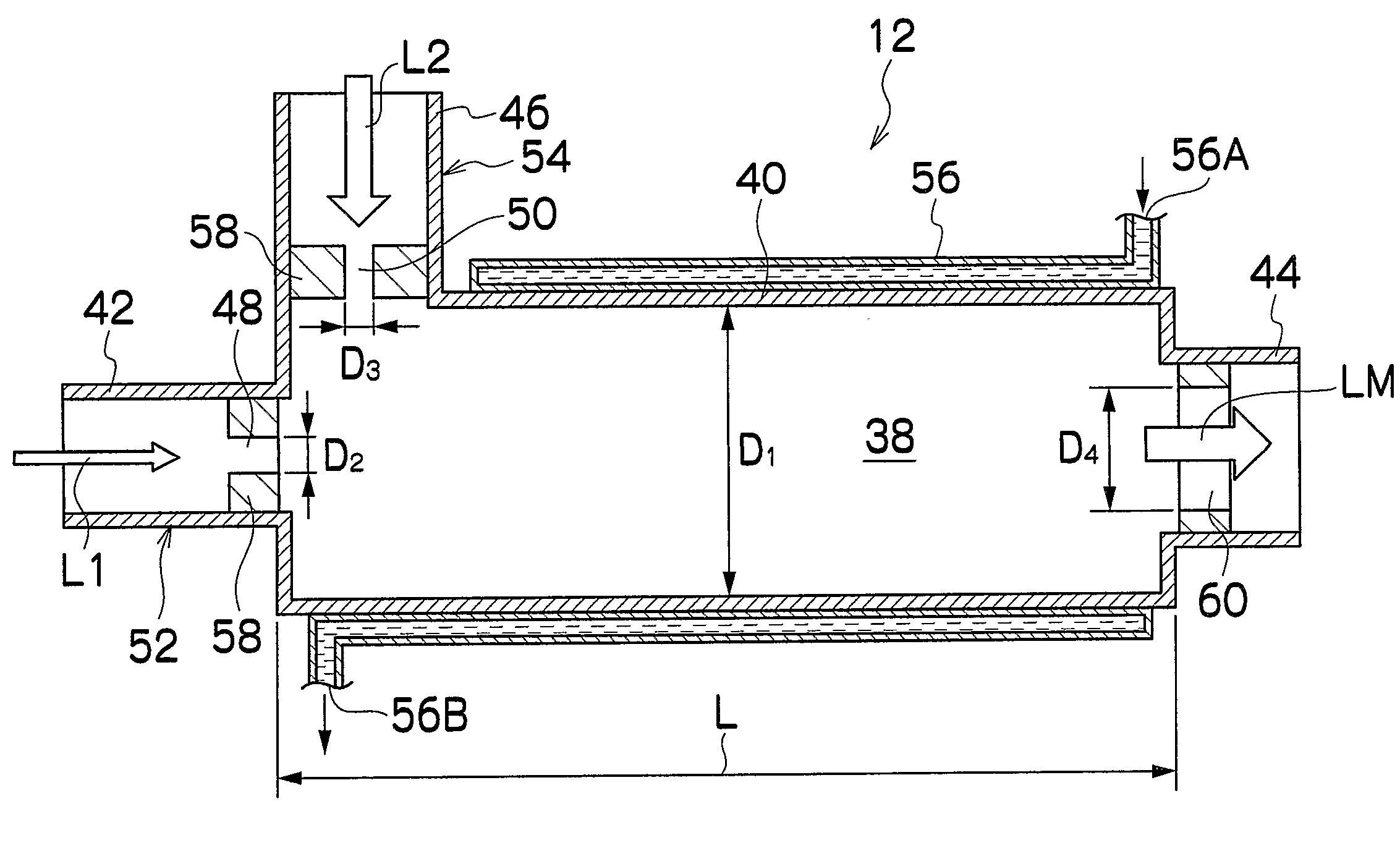
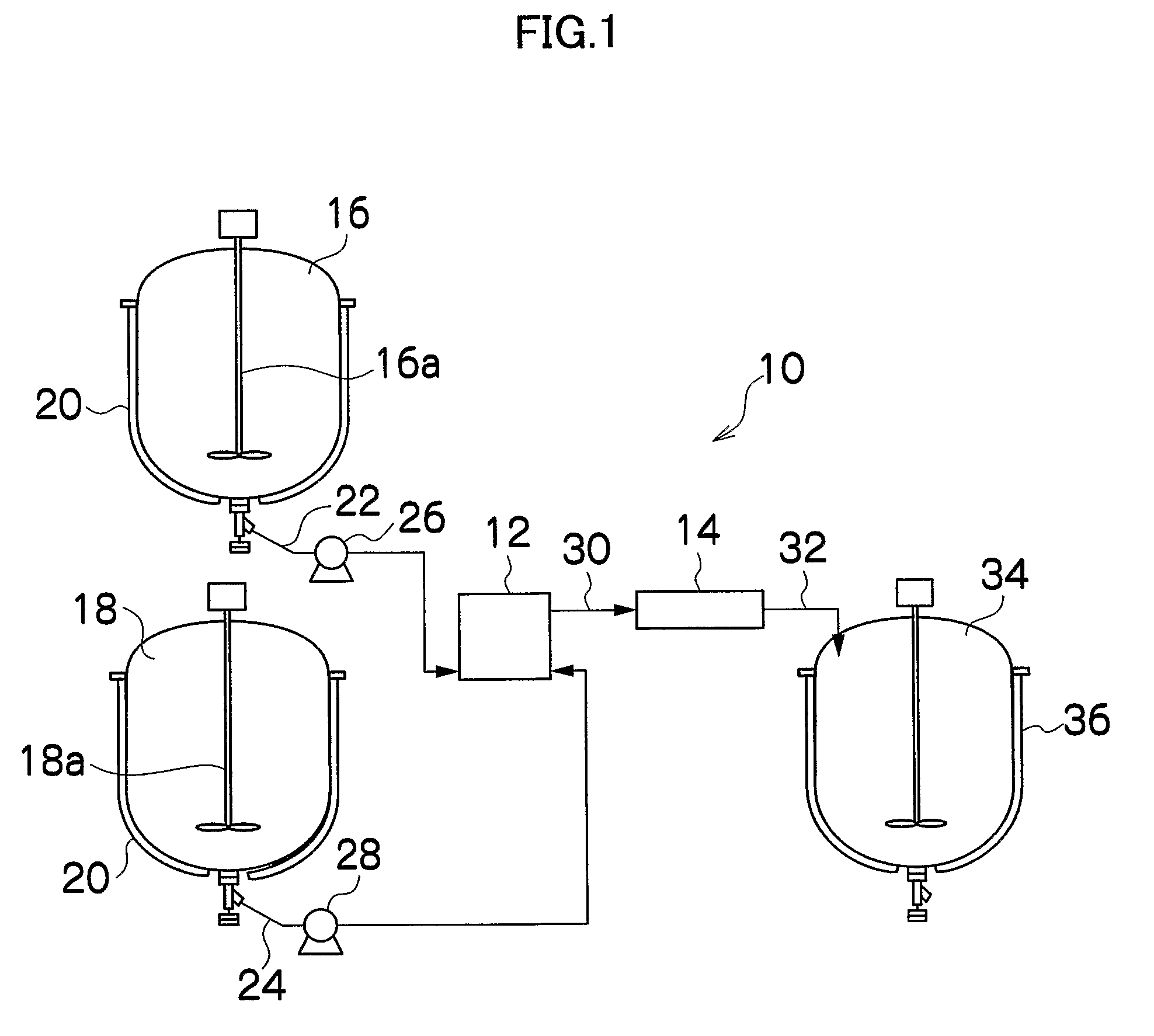
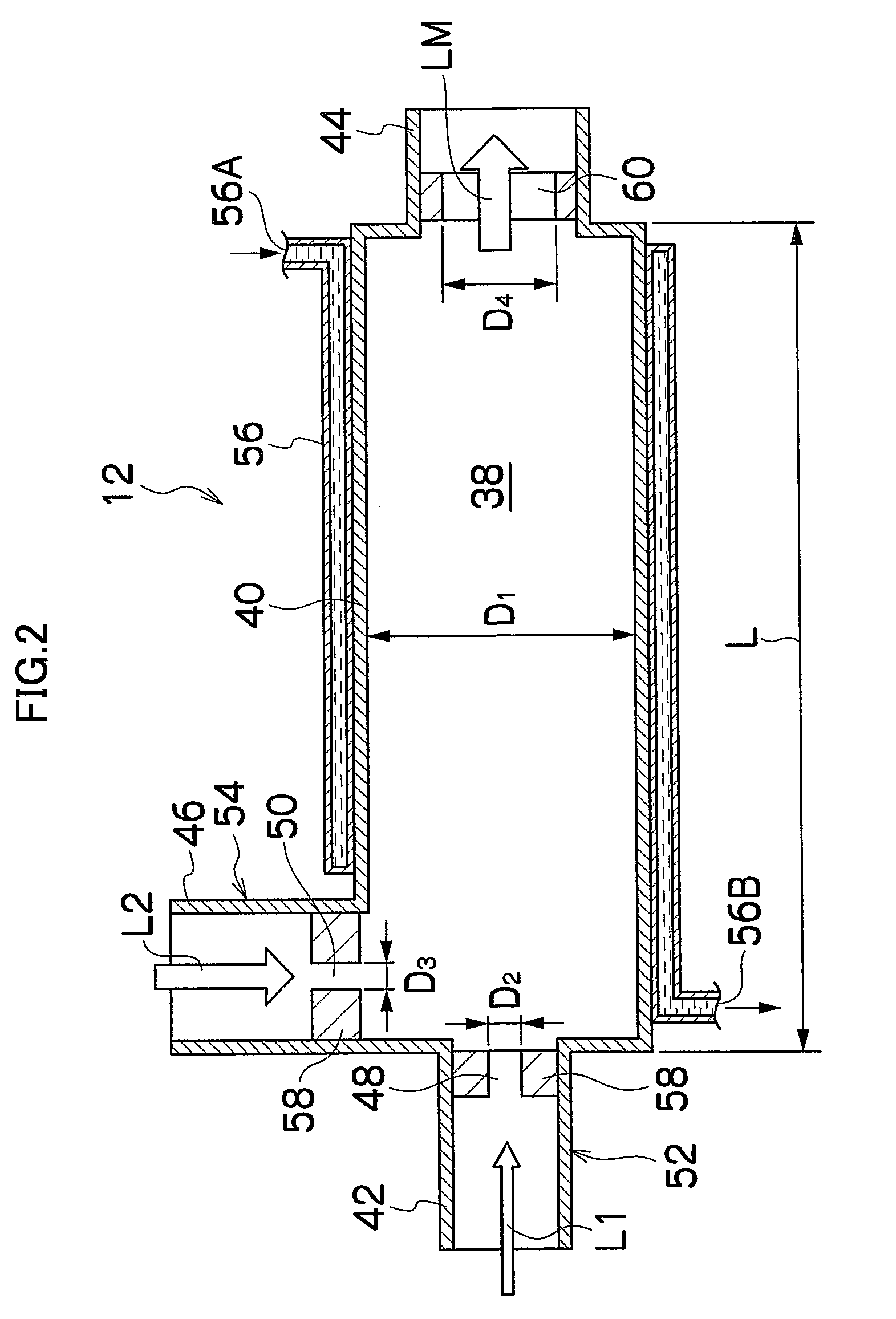
[0138]FIG. 1 is an overall structural diagram showing the reaction apparatus of the present invention and an example of continuous flow method. A reaction apparatus 10 of the present invention is applicable to any reaction system as long as gas is continuously generated with the progress of a reaction by liquid-phase reaction method (liquid-liquid reaction). The present embodiment will discuss an example of continuous manufacturing of metal fine particles included in the magnetic layer of a magnetic recording medium. Further, in Embodiment 1, two solutions of a solution L1 and a solution L2 are caused to react to manufacture metal fine particles. The solutions are obtained by dissolving, into a solvent, solutes for generating metal fine particles.

[0139]As shown in FIG. 1, the reaction apparatus 10 is mainly constituted of a sealed mixing device 12 for mixing tw...

example 1

[0202]The following is an example of Embodiment 1 of the present invention. Embodiment 1 is not limited to this example.

[0203]An operation was performed in high purity nitrogen gas as follows:

[0204]An alkene solution prepared by mixing 10.8 g of aerosol OT (Wako Pure Chemical Industries, Ltd.), 80 ml of decane (Wako Pure Chemical Industries, Ltd.), and 2 ml of oleyl amine (Tokyo Kasei Kogyo Co., Ltd.) was added and mixed in a reducer solution prepared by dissolving 0.50 g of NaBH4 (Wako Pure Chemical Industries, Ltd.) in 16 ml of H2O (deoxidized to 0.1 mg / l or less of dissolved oxygen), so that the reserved micelle solution of the first solution L1 was prepared.

[0205]An alkene solution prepared by mixing 7.0 g of aerosol OT (Wako Pure Chemical Industries, Ltd.) and 40 ml of decane (Wako Pure Chemical Industries, Ltd.) was added and mixed in a metallic salt solution prepared by dissolving 0.6 g of triammonium iron (III) trioxalate (Fe(NH4)3(C2O4)3) (Wako Pure Chemical Industries, Ltd...

embodiment 2

[0212]Embodiment 2 describes a method and apparatus for manufacturing a chemical substance according to the present invention by use of the reaction method and apparatus of Embodiment 1 of the present invention. The following is an example in which manufactured chemical substances are metal fine particles contained in a magnetic layer of a magnetic recording medium. The metal fine particles are manufactured in a continuous flow by using a solution L1, a solution L2, a solution L3, and a solution L4.

[0213]FIG. 18 is an overall structural diagram showing a production unit 200 for a chemical substance according to the present invention. A first mixing device 212 for mixing the solution L1 and the solution L2 and a degassing device 214 for removing gas generated by a reaction are similar to those of Embodiment 1. In Embodiment 2, a second mixing device 213 for adding and mixing the solution L3 is provided after the degassing device 214.

[0214]As shown in FIG. 18, the production unit 200 ...


PUM

PropertyMeasurementUnit
pressureaaaaaaaaaa
time periodaaaaaaaaaa
timeaaaaaaaaaa

Abstract

The present invention provides a reaction method for a reaction system generating gas by a reaction, comprising the steps of: providing a sealed mixing section for mixing a plurality of liquids to start a reaction and a degassing section having a gas-liquid interface for removing, from a reaction liquid, gas bubbles generated from a mixed reaction liquid, separately; and feeding the reaction liquid mixed in the mixing section to the degassing section, without being interfered by gas bubbles even in a reaction system where gas is generated by a reaction, so that it is possible to stabilize a reaction at the start of the reaction and in the progress of the reaction and stably feed liquid to a subsequent process.

Description

TECHNICAL FIELD[0001]The present invention relates to a reaction method and apparatus and a method and apparatus for manufacturing a chemical substance using the same, and particularly relates to a reaction method and apparatus in a reaction system, in which gas bubbles are generated by a liquid-liquid reaction, and a method and apparatus for manufacturing a chemical substance using the same.BACKGROUND ART[0002]When handling a reaction system where gas bubbles are generated by a liquid-liquid reaction, in order to stabilize a reaction at the start of the reaction and in the progress of the reaction, it is necessary to positively perform degassing both in a batch process and a continuous flow process. In a batch process, when mixing is performed with an agitator in a system where bubbles are trapped, shearing force is less likely to be applied to a continuous phase due to a volume change of bubbles. Thus, agitation efficiency decreases and uniform mixing cannot be performed. In a con...

Claims


Application Information

Patent Timeline
Patent Type & Authority Applications(United States)
IPC IPC(8): G11B5/00B01J14/00B01D19/00B01J19/10B01F3/08
CPCB01D19/0042H01F1/0054B01F15/065B01F2015/062B01J4/002B01J10/00B01J14/00B01J19/0066B01J19/008B01J19/10B01J19/1806B01J19/1856B01J19/1862B01J19/2405B01J19/26B01J2219/00094B82Y25/00G11B5/706G11B5/714H01F1/065H01F10/007B01F5/0256B01F25/23B01F2035/99B01F35/92B01D19/00B01F23/40
Inventor SHIRAISHI, FUMIKONAGASAWA, HIDEHARUICHIKAWA, YASUNORISUGIYAMA, SEIJIWAKI, KOUKICHI
Owner FUJIFILM CORP
Learn More