Method for controlling weld quality

a technology of quality control and welds, applied in the field of welding, can solve the problems of affecting the mechanical strength of welds, increasing the propensity for cracking and embrittlement, and deleting the effect of weld strength, so as to improve the effective heat about the electrode, improve the control of the weld bead temperature, and increase the plate heating

Inactive Publication Date: 2009-04-30
BOC LTD +1
View PDF3 Cites 16 Cited by
  • Summary
  • Abstract
  • Description
  • Claims
  • Application Information

AI Technical Summary

Benefits of technology

[0052]It will be appreciated that the provision of a shroud gas port providing a shroud gas curtain according to the present invention substantially confines the shield gas into an approximately bell-shaped envelope surrounding the weld pool. The present Applicants have found that substantially confining and concentrating the shield gas in this approach provides various weld quality improvements due the steady build up of shield gas around the weld site during a welding operation. It will also be appreciated that the apparatus and method of the invention enables recovery of the shield gas, which may be extracted from the weld site (as described above) and optionally purified and recycled. This may be especially important when welding with relatively expensive shield gases, such as helium, for example in laser welding. It will also be appreciated that recovered shield gas may be directly recycled or mixed with “fresh” gas. A sensor for the particular shield gas being employed may be installed and fresh gas automatically introduced into a flow of recycled gas in order to maintain a threshold concentration at the weld site. Alternatively, an oxygen sensor could be used to control the amount of fresh gas fed into the recycle stream. In other embodiments, the recycled shield gas may be used as the source of the shroud gas. Of course it will be appreciated that if the shield is being extracted from the vicinity of the weld at a greater rate than its supply then there will be little or no concentration increase.
[0053]The present Applicants have also found that the present invention provides improved control over the weld bead temperature during welding, which is highly desirable in various welding applications, thereby affecting the weld quality. This may be achieved by the choice of shield and shroud gases and their relative flow rates. To explain, in GMAW utilising carbon dioxide as the shield gas and / or the shroud gas tends to increase the plate heating and increases the effective heat about the electrode. Carbon dioxide forms a hot weld which may result in high splattering. Shield gas, such as argon or helium, forms a colder weld which may result in poor weld bead. The judicious combination of these two gasses during welding may complement one another to create a desirable welding environment and control over the weld quality and / or welding process.
[0054]The present Applicants have also found that the present invention provides for reduced gas consumption due to improved shielding efficiency. Further, the present Applicants have found that the present invention provides for reduced fume production rates, since there is less chance for metal vapour to react with atmospheric contaminants.

Problems solved by technology

For example, hydrogen and nitrogen absorption can affect the porosity of aluminium alloy and ferritic steel welds respectively, and therefore affect the mechanical strength of the welds resulting in, for example, an increased propensity for cracking and embrittlement.
Surface oxidation of the weld can also cause deleterious effects on the weld strength, not to mention unacceptance surface appearance.
However, the major difference between these welding processes relates to the electrodes.
However, despite the inclusion of these additives into the flux core, ingress of ambient air is still a problem and the resulting weld is still subject to the issues as described above for GMAW.
In each of the welding processes described above, the ingress of ambient contaminants into the weld zone may cause detrimental effects to the quality of the weld.
For example, effects such as: an increased risks of cracking due to embrittlement, reduced mechanical properties such as toughness, and an increased risk of surface damage.
Furthermore, ingress of ambient contaminants into the weld zone may also affect the welding process itself, for example the arc stability.
However, this process is relatively complex, requires additional circuitry and may not be suitable for all welding processes.
However, again additional circuitry is required, the method may not be suitable for all welding processes and a skilled operator is required to operate the welding torch.
However, a supplemental heat source is required and the method may not be suitable for all welding processes.

Method used


Image

  • Method for controlling weld quality
  • Method for controlling weld quality
  • Method for controlling weld quality

Examples


Embodiment Construction

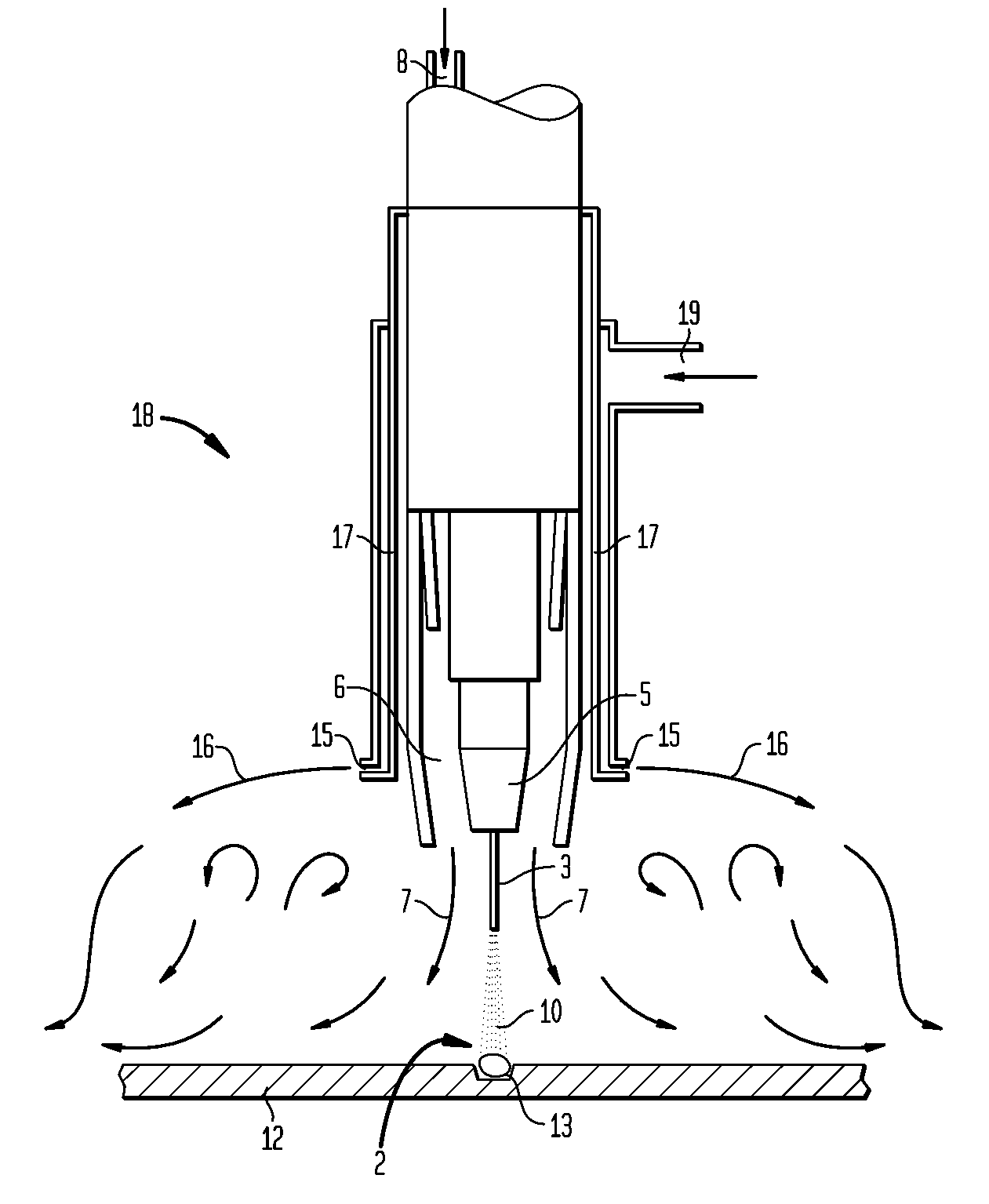
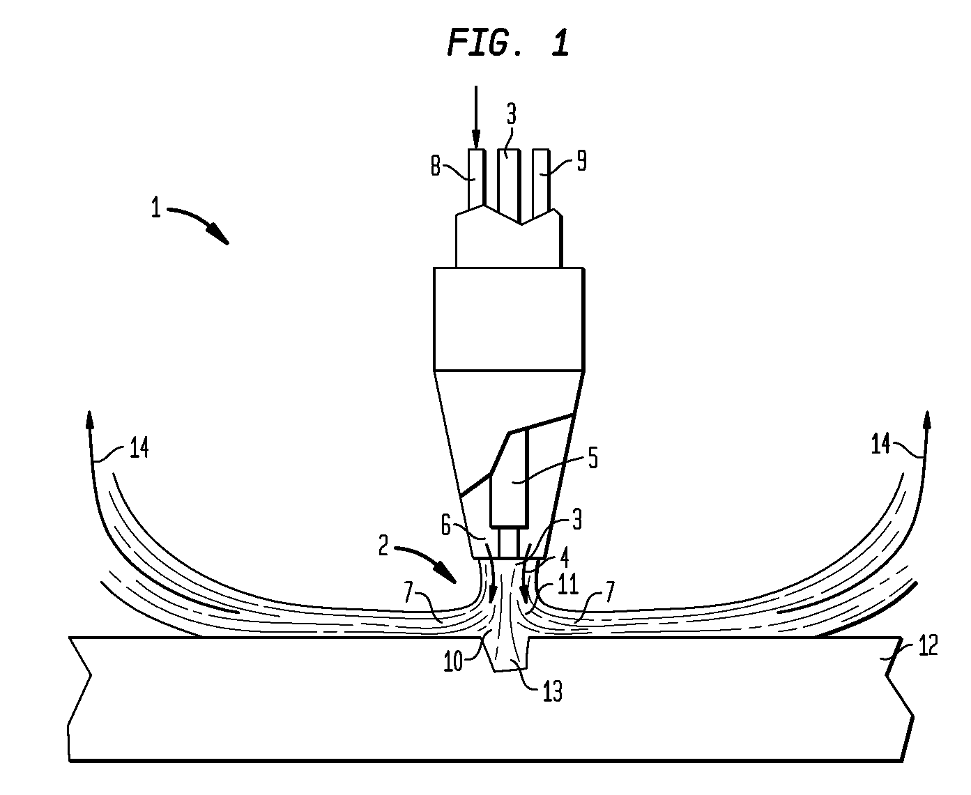
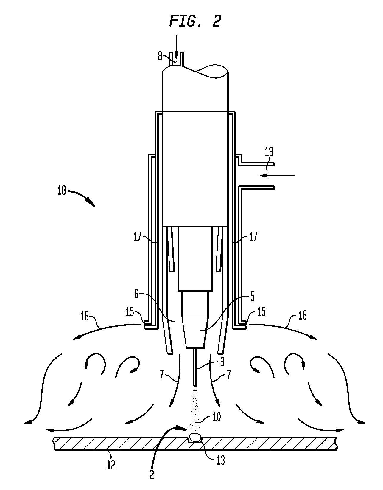
[0065]Throughout the figures presented herein like features have been given like reference numerals. Further, as will be appreciated the arrows in the Figures that represent gas flows present simplified versions of the gas flow regimes.

[0066]Referring initially to FIG. 1, a conventional GMAW torch 1 is shown comprising a heat source adapted to provide heat to welding site 2 from a consumable welding electrode 3. In the GMAW process the welding electrode 3 is a continuous welding wire 4 which is generally guided by a contact tube 5. A shield gas port 6 is also provided for passage of shield gas. The shield gas port 6 is adapted to direct a shield gas curtain 7 around the electrode 3 and the welding site 2 such that the shield gas curtain 7 closely surrounds the electrode 3. The welding wire 4 may include a fluxed core (not shown) and can be used with or without the shield gas curtain 7. The shield gas port 6 includes an upstream shield gas inlet 8, which is adapted for attachment to ...


PUM

PropertyMeasurementUnit
flow rateaaaaaaaaaa
flow rateaaaaaaaaaa
gas flow rateaaaaaaaaaa

Abstract

The present invention relates to a method for controlling weld quality. The method comprises the steps of producing a shield gas curtain around the heat source and producing a shroud gas curtain spaced radially outward from the shield gas curtain, wherein the shroud gas curtain comprises a radially outward component of velocity. The shield gas curtain and the shroud gas curtain are configured to control the resultant mechanical and/or surface properties of the weld. The present invention also relates to a method for substantially confining and concentrating shield gas about the vicinity of a welding site, and a method for substantially recovering and reusing a shield gas in a welding operation.

Description

CROSS REFERENCE TO RELATED APPLICATIONS[0001]This application claims priority from Australian Patent Application No. 2007905279, filed Sep. 26, 2007.BACKGROUND OF THE INVENTION[0002]The present invention relates to welding, and in particular to a method for controlling and improving weld quality. However, it will be appreciated that the invention is not limited to this particular field of use.[0003]The following discussion of the prior art is provided to place the invention in an appropriate technical context and enable the advantages of it to be more fully understood. It should be appreciated, however, that any discussion of the prior art throughout the specification should not be considered as an express or implied admission that such prior art is widely known or forms part of common general knowledge in the field.[0004]Welding is key enabling technology in many sectors of industry. For example, Gas Metal Arc Welding (GMAW), sometimes referred to as Metal Inert Gas (MIG) or Metal ...

Claims


Application Information

Patent Timeline
Patent Type & Authority Applications(United States)
IPC IPC(8): B23K9/00
CPCB23K9/167B23K9/325B23K9/173
Inventor NORRISH, JOHNCOOPER, PAULGODBOLE, AJIT
Owner BOC LTD
Why Eureka
Try Eureka