Low temperature bi-CMOS compatible process for MEMS RF resonators and filters

a technology of resonators and filters, applied in the field of microelectromechanical systems (mems) resonators and filters, can solve the problems of high q's and reasonable sizes, not meeting the frequency or bias voltage targets required for incorporation with analog and mixed signal circuits, and developing resonators and filters

Inactive Publication Date: 2009-04-30
IBM CORP
View PDF7 Cites 273 Cited by
  • Summary
  • Abstract
  • Description
  • Claims
  • Application Information

AI Technical Summary

Benefits of technology

[0013]Accordingly, it is an object of the present application to provide a MEMS resonator or MEMS filter having electrodes energized by an applied DC potential and excited by an applied AC po

Problems solved by technology

Resonators and filters developed to date have demonstrated high Q's and reasonably small sizes, but have not achieved the frequency or bias voltage targets required for incorporation with analog and mixed signal circuits.
Other drawbacks of current MEMS resonators and filters include incompatibility of materials, processes, and processing temperatures for integration with other IC processes, inability to scale the devices to the desired sizes because of grain size limitations of the materials used and inability to form very small gaps between electrodes, and failure to provide protection for the MEMS devices from subsequent processing steps and ambient conditions and contamination.
One of the drawbacks of the prior art is the deposition temperature of the materials commonly used for construction of the MEMS device.
This type of process integration is much more difficult to achieve and is very specific to the particular IC process.
However, this cannot be done with prior art MEMS resonators and filters.
Another serious issue with prior art MEMS resonators and filters is the process by which the devices are released from the surrounding layers and substrate.
This solution will also remove silicon nitride (SiN), although at a slower rate, and causes etching of or damage too many metals.
Because SiO2 and SiN are used as insulating layers in integrated circuits, this release method also makes it very difficult to integrate prior art MEMS resonators and filters with IC processes.
Another problem with the use of aqueous buffer-HF as a release method is the occurrence of a phenomenon known as stiction.
As the water is then removed during the subsequent drying step, the freestanding MEMS parts have a tendency to stick to the substrate or surrounding materials because of

Method used


Image

  • Low temperature bi-CMOS compatible process for MEMS RF resonators and filters
  • Low temperature bi-CMOS compatible process for MEMS RF resonators and filters
  • Low temperature bi-CMOS compatible process for MEMS RF resonators and filters

Examples


Embodiment Construction

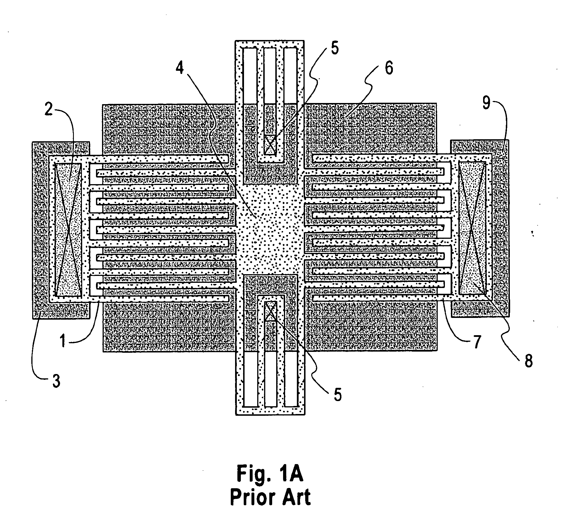
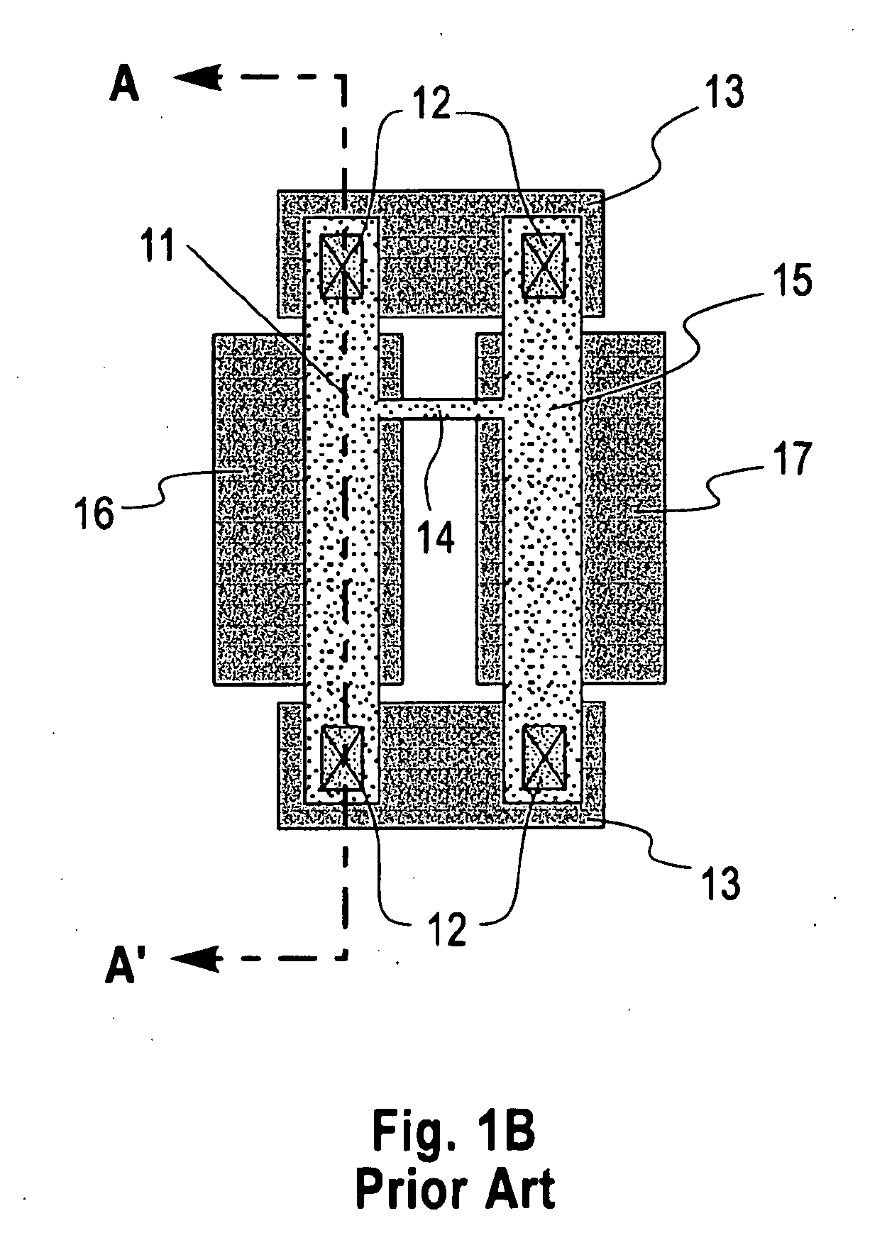
[0028]FIGS. 3-11B show cross-sectional views according to a preferred embodiment of the invention for a device such as the one shown in the prior art in FIG. 1B and in cross-section in FIG. 1C. However, MEMS resonators and filters can be designed in a wide variety of configurations including comb-drive resonators, beams fixed at two ends, beams fixed at one end, beams with suspensions, coupled beams, tuning forks, beams with bends or turns, curved beams, disks, and so on. These drawings of FIGS. 3-11B are in no way intended to exclude other geometries and configurations for building a MEMS resonator or filter, and all such geometries and configurations are included herein. The process of manufacture described is the same for all such configurations, and the design shown in FIGS. 3-11B is chosen for convenience of description only.

[0029]FIG. 2A shows a typical starting substrate 31 covered by an insulating layer 32. Starting substrates 31 may include a variety of materials such as si...


PUM


Abstract

A method of formation of a microelectromechanical system (MEMS) resonator or filter which is compatible with integration with any analog, digital, or mixed-signal integrated circuit (IC) process, after or concurrently with the formation of the metal interconnect layers in those processes, by virtue of its materials of composition, processing steps, and temperature of fabrication is presented. The MEMS resonator or filter incorporates a lower metal level, which forms the electrodes of the MEMS resonator or filter, that may be shared with any or none of the existing metal interconnect levels on the IC. It further incorporates a resonating member that is comprised of at least one metal layer for electrical connection and electrostatic actuation, and at least one dielectric layer for structural purposes. The gap between the electrodes and the resonating member is created by the deposition and subsequent removal of a sacrificial layer comprised of a carbon-based material. The method of removal of the sacrificial material is by an oxygen plasma or an anneal in an oxygen containing ambient. A method of vacuum encapsulation of the MEMS resonator or filter is provided through means of a cavity containing the MEMS device, filled with additional sacrificial material, and sealed. Access vias are created through the membrane sealing the cavity; the sacrificial material is removed as stated previously, and the vias are re-sealed in a vacuum coating process.

Description

RELATED APPLICATION[0001]This application claims priority of Provisional application, Ser. No. 60 / 339,089, filed Dec. 10, 2001.BACKGROUND OF THE INVENTION[0002]1. Field of the Invention[0003]The present invention relates to microelectromechanical system (MEMS) resonators and filters, and, more particularly, to the fabrication of such devices in a manner which allows integration with other integrated circuit technologies, such as Bi-CMOS, while maintaining the desired properties of these devices such as high resonant frequency (f0) and very high quality factor (Q).[0004]2. Description of the Prior Art[0005]Microelectromechanical system (MEMS) devices have the potential for great impact on the communications industry. MEMS RF switches, oscillators (resonators), filters, varactors, and inductors are a few of the devices that could replace large and relatively expensive off-chip passive components. It is even possible that the introduction of these types of MEMS devices, particularly re...

Claims


Application Information

Patent Timeline
IPC IPC(8): H03H9/24H01L23/28H01L21/56
CPCB81B2201/0271B81C1/0023H03H9/2405B81C2203/0735H03H3/0072B81C1/00246
Inventor BUCHWALTER, LEENA PAIVIKKICHAN, KEVIN KOKDALTON, TIMOTHY JOSEPHJAHNES, CHRISTOPHER VINCENTLUND, JENNIFER LOUISEPETRARCA, KEVIN SHAWNSPEIDELL, JAMES LOUISZIEGLER, JAMES FRANCIS
Owner IBM CORP
Why Eureka
Try Eureka