Eureka AIR delivers breakthrough ideas for toughest innovation challenges, trusted by R&D personnel around the world.

Laser processing mask and laser processing method

Inactive Publication Date: 2009-04-30
PANASONIC CORP
View PDF20 Cites 4 Cited by
  • Summary
  • Abstract
  • Description
  • Claims
  • Application Information

AI Technical Summary

Benefits of technology

[0008]The inventors of the present invention have conducted studies for preventing cracking of the negative electrode active material layer, separation of the negative electrode active material layer, and deformation of the negative electrode in lithium secondary batteries containing an alloy-based active material as the negative electrode active material. In the process of such studies, the inventors have found that the problems in the past techniques can be solved substantially by forming a regular pattern of minute projections with a height and a dimension of in the order of several micrometers on the surface of the negative electrode current collector by plastic deformation, and forming a negative electrode active material layer on the surface of the projections.
[0009]Furthermore, the inventors of the present invention have found that minute projections can be accurately formed on the surface of the negative electrode current collector by plastic deformation, by forming a pattern of recesses corresponding to the projections in size, shape, and arrangement on the surface of a roller; forming a press-contact portion by bringing two such rollers into press-contact; and passing a negative electrode current collector through this press-contact portion.
[0013]An object of the present invention is to provide a laser processing mask that is effective in forming a pattern of projections and recesses with minute dimensions in the order of several micrometers on the surface of a workpiece made of, for example, a metal material, and to provide a laser processing method using the laser processing mask.
[0014]As a result of diligent studies for solving the above-described problems, the inventors of the present invention have succeeded in obtaining a laser processing mask, in which apertures with a specific shape are formed and that is capable of accurately reproducing a pattern of projections and recesses with minute dimensions in the order of several micrometers, thereby completing the present invention.
[0026]By performing laser processing using a laser processing mask of the present invention, minute patterns of projections and recesses in the order of several micrometers can be accurately and easily formed on the surface of a workpiece such as a roller. Particularly, the shape, the dimensions (diameter, depth of the recesses, and height of projection), and the arrangement of the pattern of projections and recesses can be reproduced substantially accurately. That is, using a laser processing mask of the present invention makes it possible to provide a roller on the surface of which recesses with a shape and dimensions substantially corresponding to those of projections in the order of several micrometers are formed. By carrying out plastic deformation processing for a current collector by using this roller, projections having a shape substantially as a designed shape and dimensions in the order of several micrometers can be formed in an industrially advantageous way on the surface of the current collector.

Problems solved by technology

However, it was found that it is very difficult to form minute projections with a diameter and a height in the order of several micrometers by a general laser processing method.
However, when the size of the projections is minute, due to the fact that the roller surface tends to be in a molten state from the laser irradiation and that the roller surface is not flat, the shape of individual recesses formed on the roller surface are different from the designed shape of the projections.
Accordingly, it is very difficult to accurately reproduce the shape of the projections.

Method used


Image

  • Laser processing mask and laser processing method
  • Laser processing mask and laser processing method
  • Laser processing mask and laser processing method

Examples


example 1

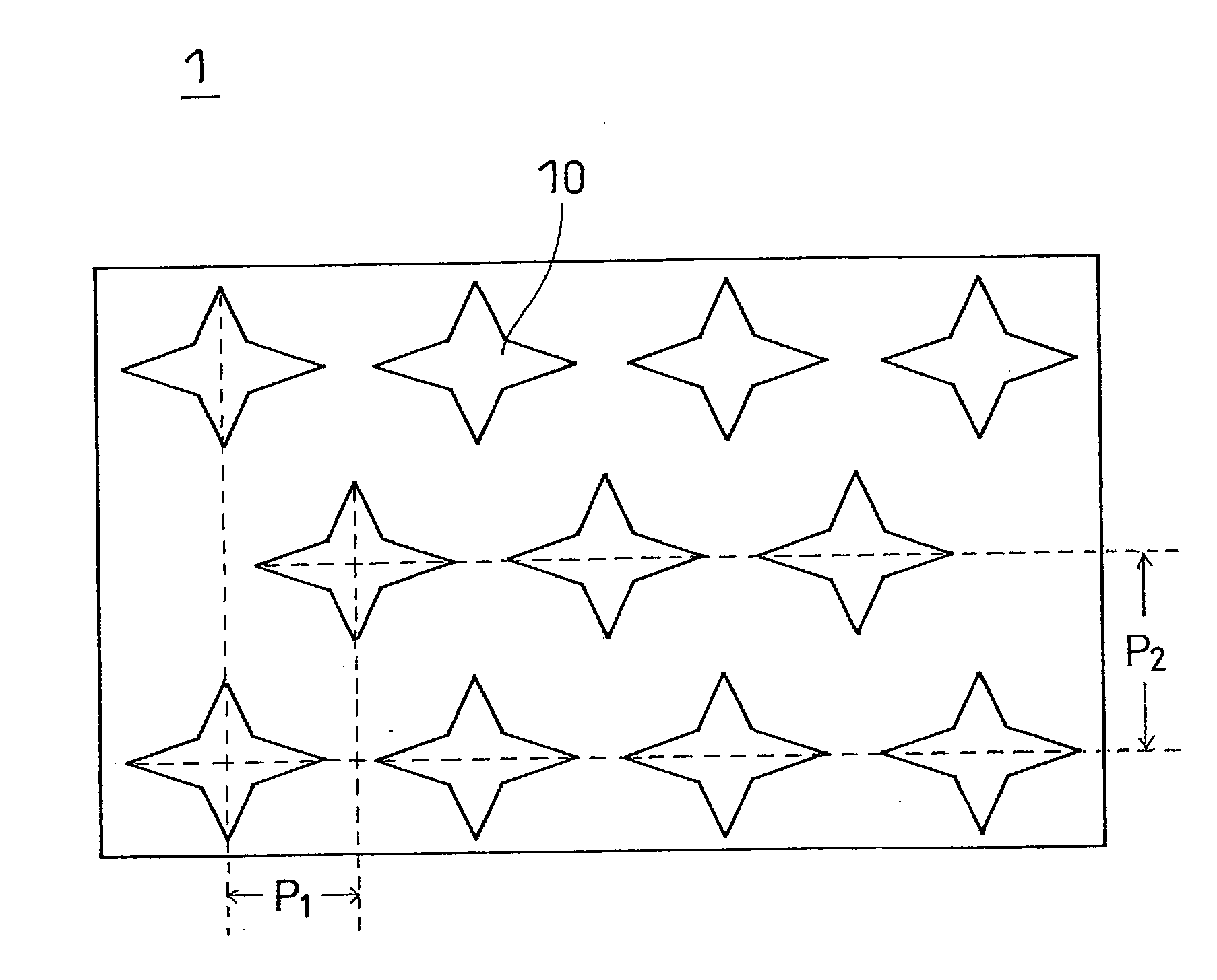
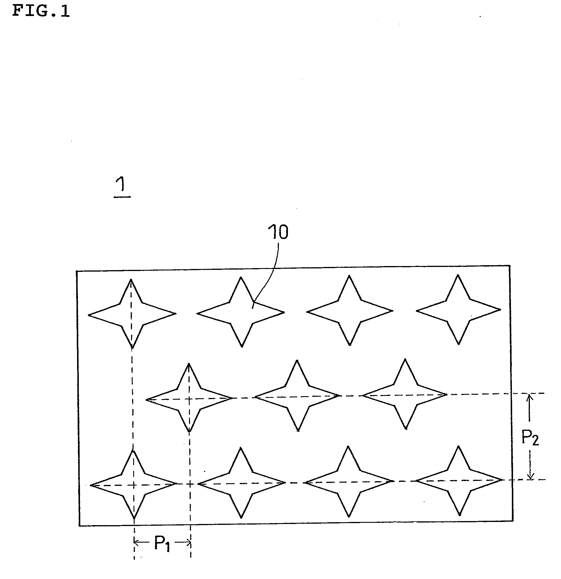
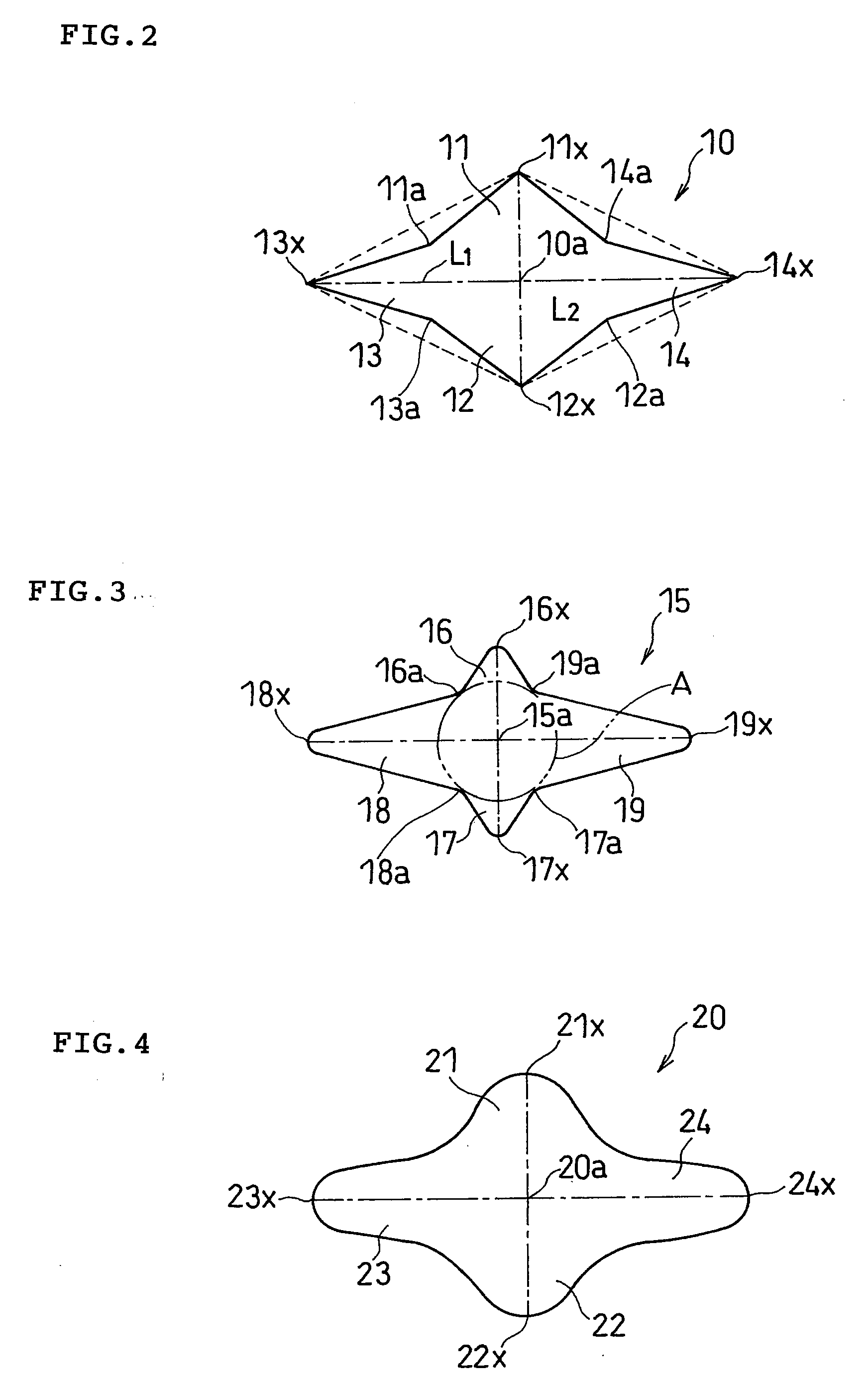
[0113]A stainless steel plate (SUS304) with a thickness of 0.3 mm, and dimensions of 22 mm×22 mm was subjected to electric discharge machining, thereby obtaining a laser processing mask of the present invention, including apertures 15 having a shape as shown in FIG. 3 and being arranged in a staggered configuration as shown in FIG. 1.

[0114]Specifically, the electric discharge machining was performed as follows using a V ram-type electric discharge machining apparatus including a head with a tungsten electrode having a tip end diameter of 8 μm attached thereto, the head being supported such that precise movement was possible by a servo motor. First, a stainless steel plate (SUS304) with a thickness of 0.3 mm and dimensions of 22 mm×22 mm was placed on the workpiece table of the electric discharge machining apparatus. Next, a power supply through an RC cirtuit was connected across the stainless steel plate and the tungsten electrode. While applying a voltage of 70 V to the tungsten el...

example 2

[0120]A laser processing mask of the present invention was made in the same manner as in Example 1, except that the aperture 15 was changed to the aperture 10 shown in FIG. 1 or FIG. 2. In the aperture 10, L1 and L2 were set to, L1: 0.32 mm and L2: 0.16 mm, and the dimensions of a rectangle formed by connecting the apexes of the indentations of the sides between the protrusions were set to: 0.16 mm×0.08 mm. This mask was made for the purpose of forming recesses having its aperture shape of a diamond with a longer diagonal line of 20 μm and a shorter diagonal line of 10 μm.

[0121]100 recesses were formed in a staggered configuration on the surface of a forged steel roller in the same manner as in Example 1, except that this mask was used. The pitch of the recess in the longitudinal direction (the longitudinal direction of the forged steel roll) was about 20 μm, and the pitch in the latitudinal direction (the circumferential direction of the forged steel roll) was about 14 μm.

[0122]As ...

example 3

[0123]A laser processing mask of the present invention was made in the same manner as in Example 1, except that the aperture 15 was changed to the aperture 20 shown in FIG. 4. In the aperture 20, L1 and L2 were set to, L1: 0.32 mm, L2: 0.16 mm, the radius of curvature of protrusions 21 and 22 were set to 20 μm, the radius of curvature of protrusions 23 and 24 was set to 30 μm, and the radius of curvature of the indentation between two protrusions was set to 30 μm. This mask was made for the purpose of forming recesses having its aperture shape of a diamond with a longer diagonal line of 20 μm and a shorter diagonal line of 10 μm.

[0124]100 recesses were formed in a staggered configuration on the surface of a forged steel roller in the same manner as in Example 1, except that this mask was used. The pitch of the recess in the longitudinal direction (the longitudinal direction of the forged steel roll) was about 20 μm, and the pitch in the latitudinal direction (the circumferential dir...


PUM

PropertyMeasurementUnit
Thicknessaaaaaaaaaa
Lengthaaaaaaaaaa
Shapeaaaaaaaaaa

Abstract

In a laser processing mask, apertures formed thereon as laser light passing apertures are shaped so that a plurality of protrusions extend radially from the center of each of the apertures to the peripheral portion thereof. By using this laser processing mask, a recess pattern with dimensions of several micrometers to several tens of micrometers and high dimensional precision and shape precision can be formed on the surface of a workpiece made of, for example, a metal material by laser processing.

Description

FIELD OF THE INVENTION[0001]The present invention relates to a laser processing mask, and to a laser processing method. More particularly, the present invention mainly relates to an improvement of apertures that are formed on a laser processing mask for applying laser.BACKGROUND OF THE INVENTION[0002]Lithium ion secondary batteries have high capacity and high energy density and their size and weight reduction can be easily achieved. Therefore, lithium ion secondary batteries are widely used as a power source for portable small electronic devices, including mobile phones, personal digital assistants (PDAs), notebook personal computers, camcorders, and portable game devices. In a typical lithium ion secondary battery, a positive electrode containing a lithium cobalt compound as the positive electrode active material, a negative electrode containing a carbon material as the negative electrode active material, and a separator of a polyolefin porous film are used. Lithium ion secondary b...

Claims


Application Information

Patent Timeline
IPC IPC(8): B32B3/10B29C35/08B23K26/00B23K26/066B23K103/04
CPCB23K26/0656B23K26/0823B41M5/262B41M5/265Y10T428/24273H01M4/72H01M10/052Y02E60/122H01M4/661B23K26/066Y02E60/10B23K2103/02
Inventor KOGETSU, YASUTAKATAGUCHI, YOSHIFUMI
Owner PANASONIC CORP
Why Eureka
Eureka Blog
Learn More