
Broadband passive distributed tuned vibration and acoustic absorber for modally dense structures

a passive distributed, tuned technology, applied in the direction of shock absorbers, building repairs, shock proofing, etc., can solve the problems of significant vibration or noise, objectionable sound, and high cost of expensive and complex sensing/actuation/feedback control/connectivity systems

Active Publication Date: 2009-05-07
DUPONT SAFETY & CONSTR INC
View PDF19 Cites 18 Cited by
  • Summary
  • Abstract
  • Description
  • Claims
  • Application Information

AI Technical Summary

Benefits of technology

[0014]In one embodiment the subject invention is a vibration absorber comprising a viscoelastic layer for distribution over a modally dense vibrating structure having an effective mass and that when excited by a broadband input excitation, the vibrating structure exhibits a frequency response spectrum in which a first and a second targeted natural frequency are

Problems solved by technology

When resonant excitation occurs within the audible frequency range (20 Hz to 20,000 Hz), the result is sound that, if of sufficient amplitude, is objectionable.
In practice this technique reduces the vibration or noise significantly but does not eliminate it altogether.
In many instances active noise reduction techniques adequately reduce vibrations and noise, but at the cost of expensive and complex sensing / actuation / feedback control / connectivity systems.
However, passive control systems can have significant mass and are typically practical only at frequencies above 500 Hz since it is at these relatively higher frequencies that the dimensions of the passive control systems are comparable with the relatively short wavelength of the vibration of the vibrating body.
Application of a passive vibration or sound control system is generally ineffective as the physical thickness is generally too large and the mass is generally too high, therefore flexibility of such systems is limited to conform to non-flat systems, such as wall cavity, spatially challenging structures, pipes.
However, a point absorber only controls the vibration or noise at one frequency at one point on the structure and is thus limited in its function to control vibrations over a large area of the vibrating body.
Thus, in a modally dense vibrating structure having multiple closely spaced natural frequencies, the application of a single degree of freedom vibration absorber tuned to one natural frequency can result in an undesirable increase in vibration and / or acoustic radiation at adjacent natural frequencies.
None of the known passive vibration and acoustic absorbers adequately controls vibration and / or acoustic radiation from modally dense vibrating structures.

Method used


Image

  • Broadband passive distributed tuned vibration and acoustic absorber for modally dense structures
  • Broadband passive distributed tuned vibration and acoustic absorber for modally dense structures
  • Broadband passive distributed tuned vibration and acoustic absorber for modally dense structures

Examples


example 1

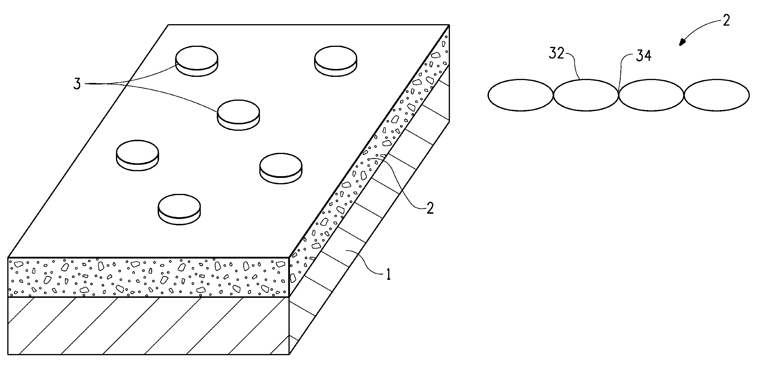
[0075]An absorber according to the invention was formed using a layer of open cell melamine foam (white Willtec® foam from Illbruck Acoustic Inc., Minneapolis, Minn.) having a patterned stiffness variation developed by quilting. The original melamine foam layer was 13 mm thick with a basis weight of 9.4 kg m3, 120 rayls specific air flow resistance, and relatively constant average normalized dynamic stiffness k* of 3,500 N / m / cm2 (determined using the test set up described herein and illustrated in FIG. 3). The foam was quilted with a 0.1 mm thick, 17 g / m2 basis weight nylon 6,6 spunbond scrim on both sides of the foam. A pattern of approximately 11 cm×11 cm diamonds was quilted into the foam, with a resultant thickness varying from 6 mm to 13 mm.

[0076]Mass elements for use in the example absorber were flat zinc coated steel disks of outer diameter of 2.54 cm with a hole in the middle and cross section area of 3.35 cm2. The ratio of the individual mass element weight to the mass cont...

example 2

[0082]An absorber according to the invention was formed using a layer of open cell melamine foam (white Willtec® foam from Illbruck Acoustic Inc.) as in Example 1, the foam layer having a normalized dynamic stiffness k* of 3,500 N / m / cm2.

[0083]Mass elements for use in the example absorber were flat zinc coated steel disks of outer diameter of 25 cm with a small hole in the middle and cross section area of 4.85 cm2. The ratio of the individual mass element weight to the mass contact area was varied by varying the mass of the individual mass elements. Three sets of mass elements having the same cross section area and different masses were selected. One set of mass elements had a mean weight of 6 g (standard deviation of 0.1) and a mass ratio μ1 of 0.0245; one set of mass elements had a mean weight of 12 g (standard deviation of 0.6) and a mass ratio μ2 of 0.0245; and one set of mass elements had a mean weight of 18 g (standard deviation of 0.03) and a mass ratio μ3 of 0.0203. The mass ...

example 3

[0088]An absorber according to the invention was formed having two viscoelastic layers and two corresponding sets of mass elements in contact with both viscoelastic layers. The absorber was adapted to a modally dense wall having studs spaced 40.64 cm apart. The first viscoelastic layer was formed from the foam layer used in Example 1. The foam was quilted with a spunbond scrim on both sides of the foam as described in Example 1.

[0089]Two sets of mass elements were selected for use in contact with the first viscoelastic layer. The first set was flat zinc-coated steel disks having an outer diameter of 2.54 cm with a hole in the middle and cross section area of 3.35 cm2. The ratio of the individual mass element weight to the mass contact area was varied by varying both mass of the individual mass elements and the contact area of mass elements. The weight of the mass elements was varied between 4.65 g and 6.6 g, with a mean weight of 5.69 g (standard deviation of 0.45). The second set o...


PUM


Abstract

A passive distributed vibration absorber that utilizes multiple discrete mass elements and a viscoelastic layer and that effectively attenuates vibration in modally dense structures excited by a broadband input noise excitation and is tunable to multiple natural frequencies in such modally dense vibrating structures including low frequencies

Description

BACKGROUND OF THE INVENTION[0001]1. Field of the Invention[0002]This invention is directed to material and methods for reducing vibration in structures.[0003]2. Description of the Related Art[0004]Resonance occurs when a frequency is introduced at which a structure naturally vibrates. When a structure is excited at one or more of its resonant frequencies (for purposes of this invention, referred to as “natural frequencies”), an amplified motion (in terms of displacement, velocity, or acceleration) response occurs. When resonant excitation occurs within the audible frequency range (20 Hz to 20,000 Hz), the result is sound that, if of sufficient amplitude, is objectionable. Objectionable vibration may occur when a structure undergoes resonant response at any frequency.[0005]Various active and passive noise reduction control techniques are known and used to control structural vibration and accompanying sound radiation. For purposes of this invention, vibration will be considered as inc...

Claims


Application Information

Patent Timeline
IPC IPC(8): E04G21/00F16F9/30E04B1/98
CPCF16F9/30F16F7/108
Inventor LEVIT, NATALIA V.LAMONTIA, MARK ALLANMELLEN, DAVID M.KING, JR., JOSEPH A.KONDYLAS, KATHLEENFULLER, CHRISTOPHER R.
Owner DUPONT SAFETY & CONSTR INC
Learn More