Cooling methods and systems using supercritical fluids

a supercritical fluid and cooling method technology, applied in the field of supercritical fluid cooling methods and systems, can solve the problem of physically impossible “vapor lock” and achieve the effect of reliable, rapid and reliable heat absorption and dissipation, and maximum efficiency

Inactive Publication Date: 2009-05-07
CRYOMECHANICS
View PDF24 Cites 12 Cited by
  • Summary
  • Abstract
  • Description
  • Claims
  • Application Information

AI Technical Summary

Benefits of technology

[0024]Considering the cooling problem from the application point of view for supercritical fluids, and recognizing all the deficiencies of the prior art, it is the primary objective of the present invention to form novel methods and systems using supercritical fluids that provide maximum efficiency and the reliable absorption of heat within the microchannels that are in direct thermal contact with the objects to be cooled.
[0025]Another objective of the invention is to provide rapid and reliable heat absorption and dissipation using nearcritical and supercritical states of refrigerants.
[0026]The next objective of the invention is to employ specific thermodynamic properties of the refrigerants in their supercritical state that is intermediate between liquid and gas. In the vicinity of the critical point of pressure and temperature, the dynamic viscosity of the supercritical fluid is near that of the normal gaseous state and much less than

Problems solved by technology

The new cooling methods and systems ma

Method used


Image

  • Cooling methods and systems using supercritical fluids
  • Cooling methods and systems using supercritical fluids
  • Cooling methods and systems using supercritical fluids

Examples


second embodiment

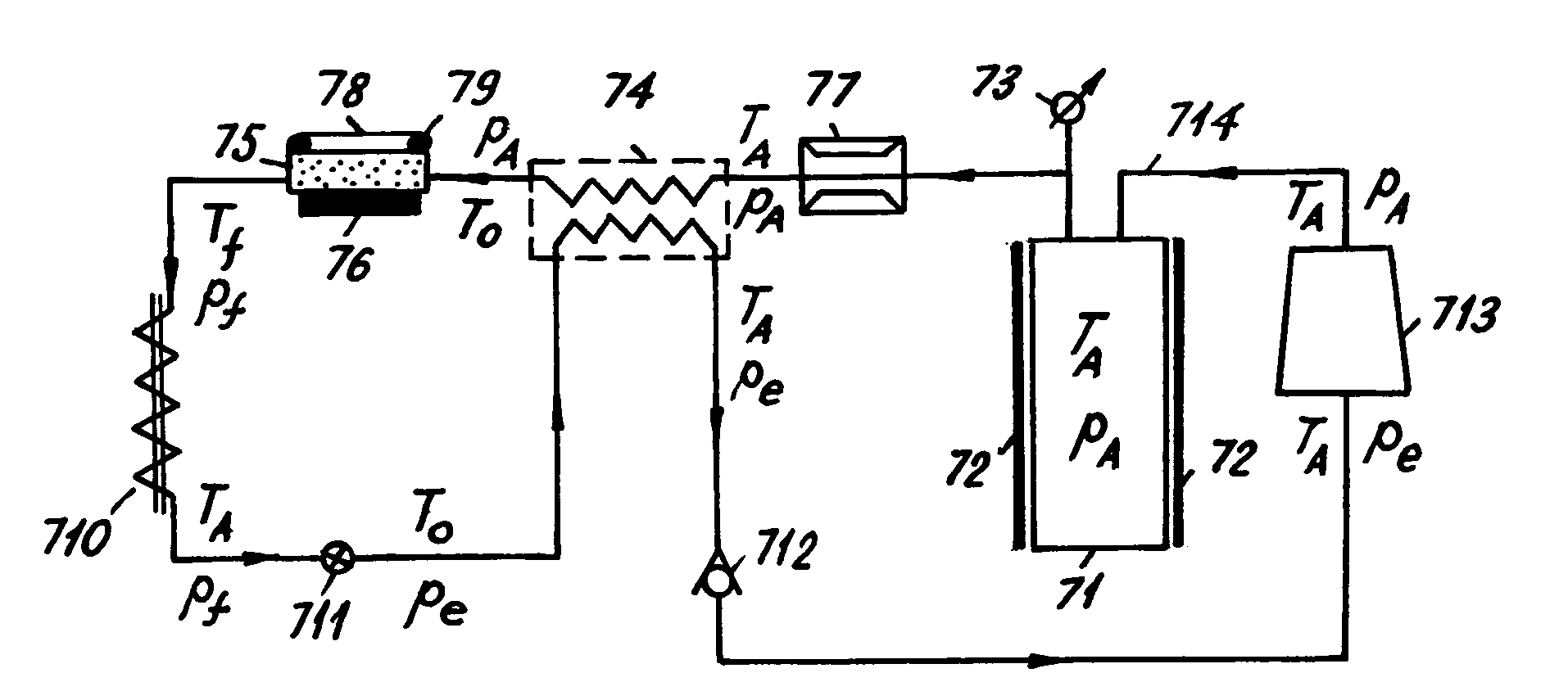
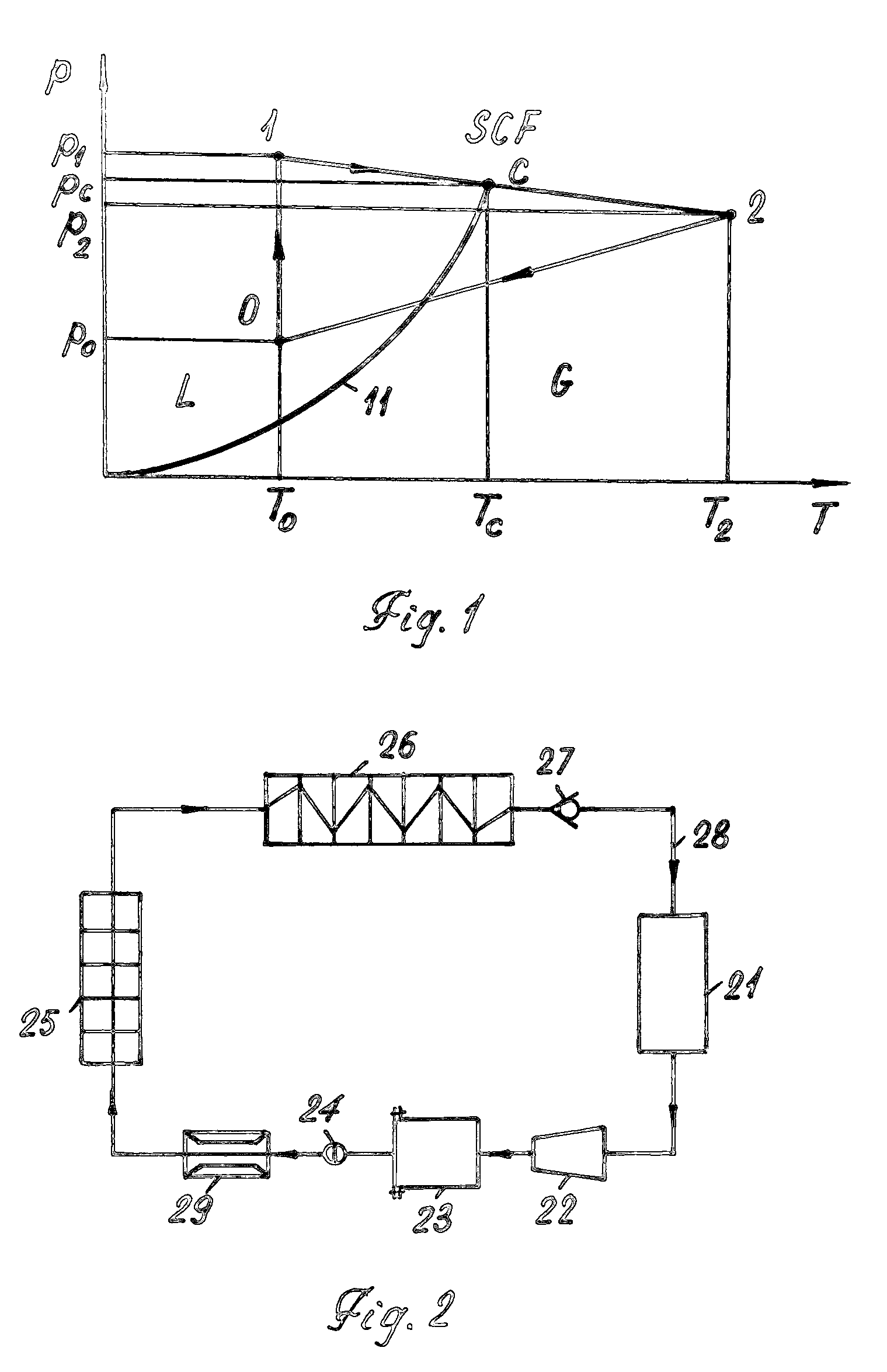
[0048]a new cooling system using carbon dioxide in a SCF state is shown in FIG. 7 and FIG. 8. The latter is a schematic phase diagram of carbon dioxide where L-G-SCF phases coexist. FIG. 7 and FIG. 8 describe an internal cooling mechanism that enables a wide temperature management range from −30° C. to ˜100° C. or even wider.

[0049]FIG. 7 shows liquid carbon dioxide enclosed in a standard reservoir 71, having a commercial heater 72, that maintains temperature TA of the reservoir slightly above the critical temperature Tc of carbon dioxide corresponding to the pressure pA above the critical pressure pc inside the range of 7.6-8.3 MPa. These temperature-pressure conditions correspond to the SCF state of carbon dioxide shown in FIG. 8. The necessary pressure pA inside the reservoir is maintained by monitoring an electric pressure gauge 73.

[0050]The SCF flowing from the reservoir is cooled first by a counterflow heat exchanger 74, to reach the temperature T0, and a temperature decrease f...

third embodiment

[0053]the present invention is shown in FIG. 9 and FIG. 10 having the same notations as in FIG. 7 and FIG. 8. This cooling system is based on an open cooling cycle when produced exhaust gas is simply discharged to the atmosphere at point 101 shown in FIG. 10.

CONCLUSION, RAMIFICATIONS, AND SCOPE

[0054]Presented cooling methods and systems using supercritical fluids may be effectively employed for numerous engineering applications in which it is necessary to provide effective and reliable cooling of critical objects with high heat emissions. Heat transfer from critical objects depends primarily on the thermodynamic properties of the refrigerants as well as on the flow rate and surface area of the object to be cooled. Microchannel cooling has distinct advantages due to a significant increase in surface area. Conventional two-phase microchannel cooling has some important deficiencies due to complex transient regimes of the liquid refrigerant related to bubble nucleation, “vapor lock”, an...


PUM


Abstract

The methods and systems using supercritical fluids for cooling of objects with high thermal emissions are disclosed. The unique thermodynamic properties of supercritical fluids combined with microchannel cooling technology allow effective absorption of the waste heat and exclude “vapor lock”, “boiling crisis”, and other deficiencies of conventional two-phase liquid cooling.

Description

CROSS REFERENCE TO RELATED APPLICATIONS[0001]This Patent Application is the continuation of an earlier application of, and claims the benefit of the filing date of, U.S. Provisional Patent Application Ser. No. 60 / 985,091 entitled “Cooling Method and Systems Using Supercritical Fluids” filed on Nov. 2, 2007.FEDERALLY SPONSORED RESEARCH [0002]Not ApplicableSEQUENCE LISTING OR PROGRAM [0003]Not ApplicableBACKGROUND OF THE INVENTION[0004]1. Field of the Invention[0005]The present invention relates to cooling methods and systems that employ refrigerants in their supercritical state combined with microchannel cooling technology in closed or open cooling cycles.[0006]2. Prior Art[0007]Reliable and effective cooling methods and systems are one of the basic problems in development of future electronic equipment, jet and internal-combustion engines, spacecraft systems and structures, fuel cell technologies, infrared radiation detectors, nuclear power generation, and others.[0008]Cooling elect...

Claims


Application Information

Patent Timeline
IPC IPC(8): C09K5/00
CPCC09K5/041C09K5/042F25B2309/061F25B9/008F25B40/00C09K5/045Y02P20/54
Inventor BABKIN, ALEXEI V.DUNCAN, ROBERT V.EFREMOV, ANATOLY I.LITTRUP, PETER J.
Owner CRYOMECHANICS
Why Eureka
Try Eureka