Filtration with internal fouling control

a technology of internal fouling and filtering, which is applied in the field of filtering with internal fouling control, can solve the problems of large equipment footprint, large format, and large equipment footprint, and achieve the effect of reducing the number of filtration operations, and improving the efficiency of filtration operations

Active Publication Date: 2009-05-14
DANISCO US INC
View PDF10 Cites 57 Cited by
  • Summary
  • Abstract
  • Description
  • Claims
  • Application Information

AI Technical Summary

Benefits of technology

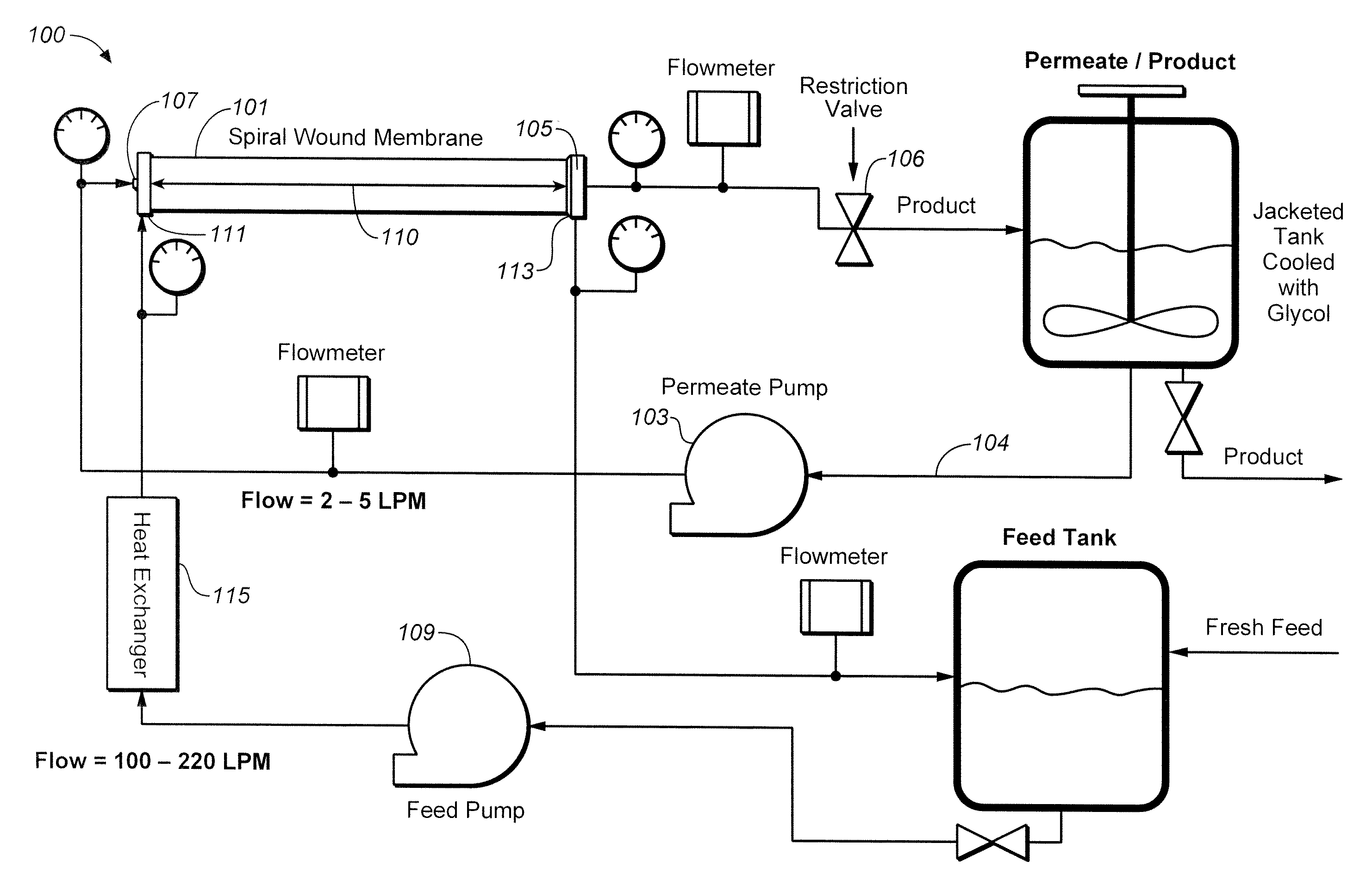
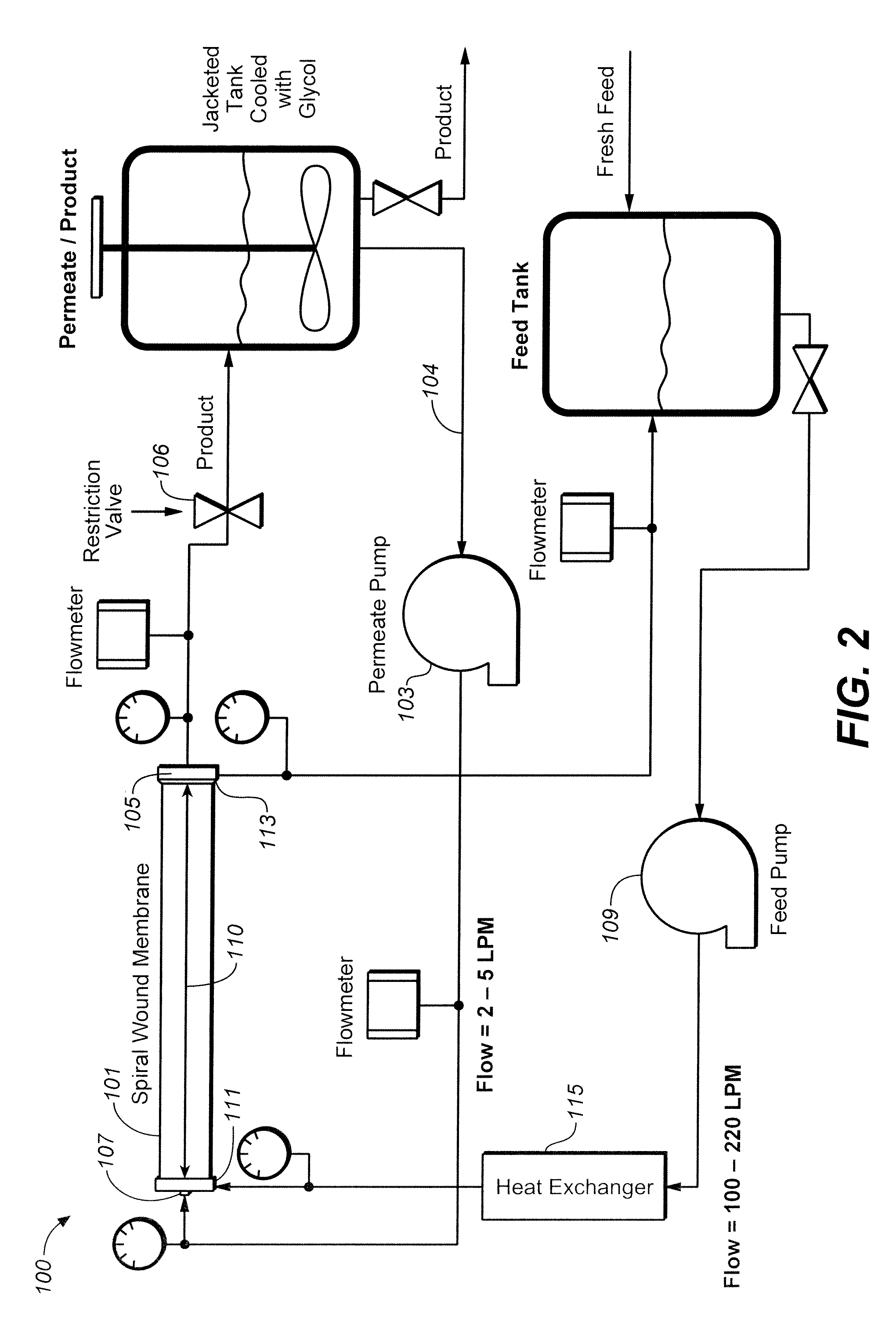
[0012]In one aspect, the invention provides a filtration process comprising providing a membrane module including a membrane defining opposing permeate and retentate sides, an inlet and an outlet, a feed stream flowing from the inlet to the outlet axially along the retentate side of the membrane, a permeate stream flowing axially from the inlet to the outlet along the permeate side of the membrane, and a permeate recirculation loop for providing co-current permeate recirculation flow to the module; adjusting the flow rate or pressure on the permeate or retentate side of the membrane to provide baseline pressures at the inlet and the outlet on the permeate and retentate sides of the membrane such that the difference in baseline pressures between the permeate and retentate sides of the membrane is substantially the same at the inlet and the outlet, wherein the baseline pressure on the permeate side of the membrane is greater at the inlet than the baseline pressure at the outlet and the baseline pressure on the retentate side of the membrane is greater at the inlet than the baseline pressure at the outlet; and periodically adjusting the pressure on the permeate side of the membrane to reduce the difference in pressures between the permeate and retentate sides of the membrane at the inlet and the outlet by at least about 50% relative to the difference between the baseline pressures. In one embodiment, the membrane is a spiral wound membrane.

Problems solved by technology

This format, however, is relatively expensive and requires a large equipment footprint when used for industrial scale operations.
However, ceramic tube systems are generally very expensive and require more power than other microfiltration systems in order to maintain the very high cross flows needed to minimize fouling.
They are not as operationally robust or as easy to run and operate as ceramic tubes, but are less costly and require a much smaller equipment footprint than ceramic tubes or plate and frame systems.
Applications of spirals at a commercial scale have been largely confined to treatments of highly dilute (low solids) process fluids.
However, spiral wound membranes tend to foul at a high rate.
Unfortunately, the trans-membrane pressure (TMP) at the inlet of a spiral wound membrane is much higher than the TMP at the outlet.
Thus, optimal TMP condition can typically only be achieved within a relatively short zone along the membrane.
Upstream of this optimal zone the membrane is overpressurized and tends to foul, while downstream of this zone the low TMP results in suboptimal flux.
Spiral wound membranes are often run in series, which exacerbates the fouling problem.
In the past, backpulsing strategies have not provided uniform local transmembrane pressures along the permeate side of the membrane.
Therefore, the level of localized defouling and flux restoration has varied considerably and unpredictably along the axial length of the membrane.
In prior backpulsing approaches, either insufficiently low backflow pressure was developed within the permeate space resulting in suboptimal cleaning, or high backflow pressures developed within the permeate side sufficient to induce some level of defouling would lead to membrane damage by delamination.
Backpulsing based on such permeate flow reversal techniques may generate a hydrodynamic shock wave or water hammer effect for inducing defouling, which is hard on the membrane.
Also, the level of any flux restoration and defouling achieved tends to progressively decline after multiple filtration cycles using such backpulsing treatments.
However, some spiral membranes in particular may not be robust enough to tolerate pneumatic backpulsing.
However, modalities expected to cause non-uniform backpressure in the filtrate passage during backpulsing are undesirable as any defouling effects achieved on the membrane also will tend to be non-uniform.
Also, ceramic filters generally are more costly than some other MF formats, for example, spiral membranes, and will offer less working surface area per length than a spiral format.
The use of external harsh chemicals and significant production down times associated with their use to clean filters is non-ideal.
Unfortunately, the hydrodynamics of spiral wound membranes have previously made this type of process very inefficient with polymeric spiral wound membranes, due to the development of a layer of polarized particles that eventually forms during operation.

Method used


Image

  • Filtration with internal fouling control
  • Filtration with internal fouling control
  • Filtration with internal fouling control

Examples


example 1

[0212]In Runs 1-4, VCF experiments were conducted on a fermentation broth using Alfa Laval 0.2 μm nominal pore size polysulfone (PS) membranes. The host organism and enzyme in the feed broth is a B. subtilis broth and protease enzyme, obtained as FNA broth from Genencor Division, Danisco US, Inc. The operating temperature was 15° C., the broth pH was 5.8, and 3 mm diameter solid plastic balls were used as a flow resistance element (FRE). The FRE were packed into the collection tube of the spiral wound membrane until they filled the tube between its axial ends and held into place with perforated disc plates at each end of the tube. UTMP and UTMP / rUTMP modes of filtration operation were evaluated. Two different ways to over-pressurize permeate were initially evaluated, which were slowing the feed pump or speeding up the permeate recirculation pump.

[0213]Runs 1-4 were conducted under the following conditions. Run 1 was a control run in which no UTMP was applied. The average TMP was 1.5...

example 2

[0216]In Runs 5-11, VCF experiments were conducted on a different fermentation broth using a similar process lay out indicated for Example 1 where different membranes also were evaluated including a Koch 1.2 μm nominal pore size spiral membrane as a control, an Alfa Laval 0.2 μm nominal pore size polysulfone (PS) membrane as a control and also for active permeate collection, and Microdyn 0.05 μm nominal pore size polyethersulfone membrane as a control and also for active permeate collection. The host organism used for producing the feed broth was B. subtilis broth and the enzyme was a protease enzyme, obtained as FN3 broth from Genencor Division, Danisco US, Inc. The operating temperature was 15° C.

[0217]Runs 5-11 were conducted under the following conditions. Run 5 was a control run using the Koch spiral membrane (Koch Membrane Systems, Inc.) in which there was only passive collection of permeate, meaning there was no UTMP nor co-current permeate recirculation (i.e., no active perm...

example 3

[0220]Experimental studies were conducted to investigate distribution of pressure drop from inlet to outlet in a permeate collection tube fitted with a tapered insert installed within the collection tube as a flow resistance element. To achieve accurate results an actual membrane of a spiral membrane system, Koch Membrane Systems, Inc., was unwrapped and removed and the permeate collection tube inside was separately used for these experiments. The permeate tube was retrofitted so that water could be injected in a sealed manner at regular intervals along the length of the tube and the local pressure and flow rate measured at the injection sites while the other tube openings along the length of the tube were blocked. The tube had inlet and outlet openings at its opposite ends for introduction of recirculated water or other test permeate and discharge of the permeate / water collected within and passing through the particular tube. Referring to FIG. 25, for purposes of this experiment, t...


PUM


Abstract

Filtration processes and systems are provided for the separation of a filterable fluid stream by a filtration membrane module with uniform transmembrane pressure and flux along the membrane and internal control of membrane fouling via intermittent periodic reduction of the pressure differential between the permeate and retentate sides of the membrane and / or backwashing cycles during separation, recovery, and / or purification of proteins, peptides, nucleic acids, biologically produced polymers and other compounds or materials from aqueous fluids.

Description

CROSS-REFERENCE TO RELATED APPLICATIONS[0001]This application claims the benefit of U.S. Provisional Application No. 60 / 971,769, filed on Sep. 12, 2007, which is incorporated by reference herein in its entirety.INTRODUCTION[0002]The section headings used herein are solely for organization purposes and are not to be construed as limiting the subject matter described in any way.[0003]The present invention pertains to filtration with internal fouling control, and, particularly, filtration using membranes providing uniform transmembrane pressure and internal fouling control for liquid / solid separations.BACKGROUND[0004]Microfiltration and ultrafiltration have been used for separation of compounds in biological broths or other liquids. The beverage industry has employed microfiltration to clarify beer and wine and in the dairy industry microfiltration and ultrafiltration can be used for processing of, for example, cheese whey or milk. Microfiltration has also recently been applied to the ...

Claims


Application Information

Patent Timeline
Patent Type & Authority Applications(United States)
IPC IPC(8): B01D65/08B01D61/22
CPCB01D61/14B01D65/00B01D65/02B01D65/08B01D2311/06B01D2321/02B01D2321/04B01D2321/10B01D2321/12B01D2321/20B01D2321/2008B01D2321/2083B01D63/10B01D2313/19B01D2311/14B01D2311/165
Inventor BECKER, NATHANIEL T.BRAUN, RYSZARDCHRISTENSEN, JR., ROBERT I.EKBOM, STEFANFONG, ROBINSCHULER, ALEXANDRA
Owner DANISCO US INC
Why Eureka
Try Eureka