

Method, Drilling Machine, Drill bit and Bottom Hole Assembly for Drilling by Electrical Discharge by Electrical Discharge Pulses
a technology of pulses and drill bits, applied in the field of plasma drilling, can solve the problems of increasing pressure requirements, local rock fracture and fragmentation, and thereby provoking controversy of machines, and achieve the effect of increasing the drilling speed
Active Publication Date: 2009-05-28
UNODRILL
View PDF2 Cites 106 Cited by
- Summary
- Abstract
- Description
- Claims
- Application Information
AI Technical Summary
Benefits of technology
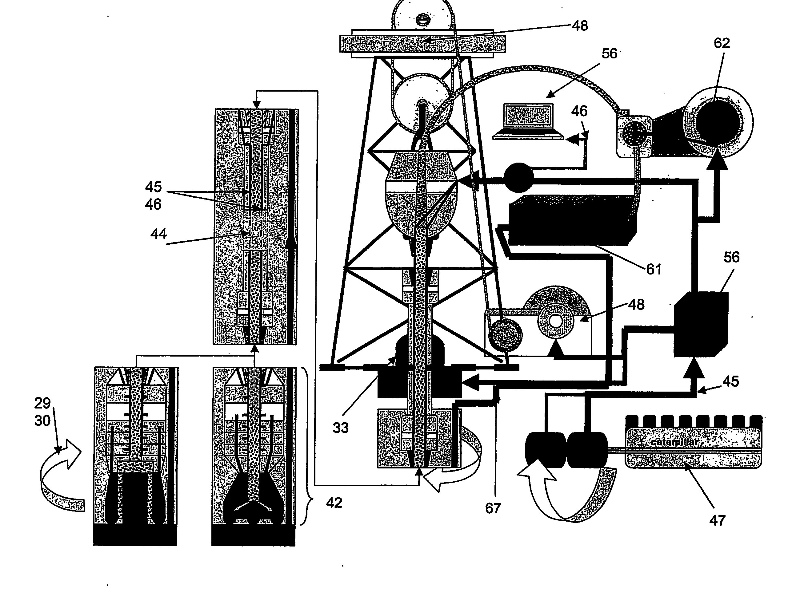
[0020]A novelty of the invention is also the hydraulic energy interaction in the drilling process, consisting of a circulation loop for discharge fluid under high pressure to flow from a pump, said pump in one form of the invention being located down-hole and in another at the surface and connected to the drill-bit by suitable pipes or hoses, through nozzles incorporated in the drill-bit, said nozzles having novel placement and direction for the purpose of cuttings removal from under the bit, thereby cleaning the hole bottom efficiently, said circulation loop finally incorporating return flow through the annular space around the drill-bit back to a discharge fluid cleaning and cuttings removal and storage system, which in one form of the invention is located down-hole and in another at the surface and from which the fluid is re-circulated in the borehole after cleaning, said cuttings removal system in the form when a ring-shape cross-section is cut, also incorporates a cutting and hoisting arrangement for the remaining cylindrical volume of cuttings which is left as a core in the borehole after the ring has been cut, to be hoisted to the surface in one piece.
[0076]In this preferred form of embodiment “C”, the entire bottom hole drilling assembly is connected to the surface by a single steel wire rope said rope having an electric cable integrated in it for signal transfer and power transfer at a practical voltage level and the borehole is fluid filled only if formation fluid pressures or stability require it. When drilling in dry, hard rock the hole drilled with this embodiment of the invention will be fluid filled only to the top of or slightly above the cuttings chamber. In either case, the circulation will be limited to a length of borehole corresponding to the combined length of the bit and core barrel, the pulse generator or generators and the pump, and the cuttings chamber and cleaning system, said combined length estimated at 2-3 times the length of the core barrel. The energy consumption, both hydraulic and bit energy correspondingly will be greatly reduced compared to full profile borehole drilling with circulation back to the surface.
Problems solved by technology
The extremely rapid expansion of this plasma channel within the rock, which occurs in less than a millionth of a second, causes the local region of rock to fracture and fragment.
The machine is thereby potentially controversial from a safety perspective and vulnerable from an insulator breakdown viewpoint for all deeper holes.
The concentric twin-pipe concept with its inner annulus dictated by the insulator requirements also infringes on the cross-sectional area of the outer annulus where the cuttings are to pass through thereby increasing pressure requirements, limiting cuttings' size and potentially contributing to the stoppage of flow.
The plurality of electrodes divided in two sets, one high-voltage and one grounded, rigidly arranged relative to each other and only allowed a small sector rotation as a unit around the axis of drilling progress represents another serious drawback from the viewpoint of pulse energy application or, in other terms, pulse energy management:
One will, and whichever for a given pulse turns out to constitute the other half of the pair will, because of the rigid electrode configuration, be separated from the bottom by a smaller or larger liquid-gap thereby forcing the pulse to go off partly in liquid and partly in the bottom matrix thereby obscuring the energy efficiency and slowing down the drilling progress.
The concept of plurality of electrodes in each set of electrodes contains another drawback.
It overlooked however that another occurrence will be an electrode pair of opposite charge in contact with the hole-bottom, but with such distance between them that the spark will not fly at the given pulse voltage level or it flies in liquid, thereby reducing efficiency and drilling progress.
The consistent placement in the state of the art concept of an electrode, normally a high-voltage electrode in the centre of the borehole constitutes a specific drawback.
A serious drawback in the state of the art electro pulse drilling concept is that there are no or minimal remedies incorporated to cause the cuttings to exit from its indigenous cavity.
Compared to other drilling practices and the hydraulic energy utilized there in order to remove much less dug-in cuttings it would appear totally inadequate.
Lack of efficiency in bottom hole cleaning is widely known from drilling practices in general as a major cause of reduced drilling progress.
This is another facet of inadequate bottom hole cleaning which constitutes a serious drawback by slowing the drilling speed.
Arc plasma drilling has never been successful in high speed operations.
Method used
View moreImage
Smart ImageViewing Examples

Examples
first embodiment
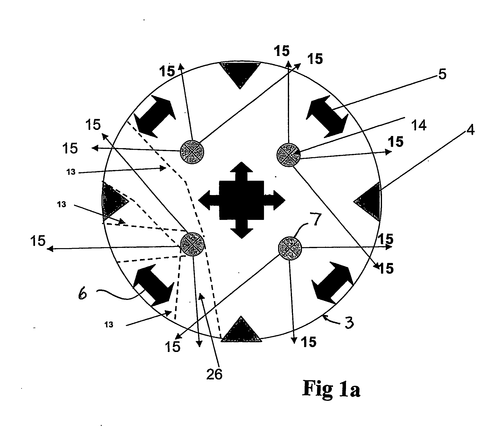
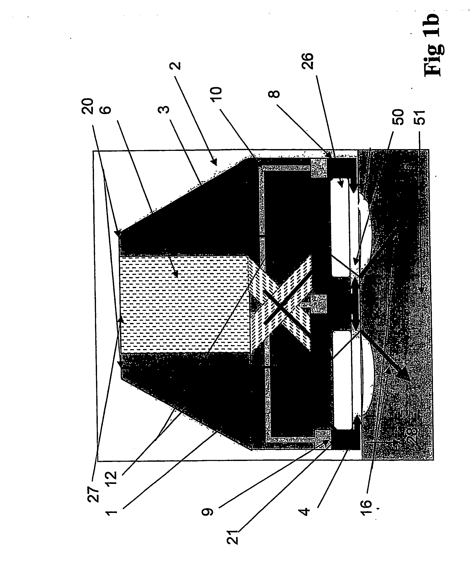
[0086]FIG. 3a shows an axial section through a drillbit,
second embodiment
[0087]FIG. 3b shows an axial section through a drillbit,
[0088]FIG. 3c-f shows an axial section through further embodiments of a drillbit FIG. 4a shows an axial section through a first embodiment of a bottom hole assembly,
[0089]FIG. 4b shows an axial section through a second embodiment of a bottom hole assembly,
third embodiment
[0090]FIG. 4c shows an axial section through a bottom hole assembly,
Login to View More PUM
 Abstract
Machine for ground drilling, with a circulating fluid, by the utilization of electric discharge generated by high-voltage pulses between electrodes. It may comprise: —A drill-bit 1 with electrodes movable relative to each other, so that bottom-hole physical contact be secured for all the electrodes 4 on all bottom-hole topographies. —Pointed hydraulic nozzles for jetting the fluid, to remove primary cuttings and with pressure expansion across the nozzles 7 at no less than 4 MPa. —A high-voltage pulse generator deployed down-hole at a minimum distance from the drill-bit 1. —A rotating or oscillating bit causing the borehole cross-sectional excavation to occur, and electric discharge between a plurality of electrodes situated on the bit face along one or a few radii and tangents. —A bottom hole assembly for annular hole-making with core storage, transportation, down-hole closed loop discharge fluid circulation. A discharge fluid storage may be incorporated. A drilling method is also described.
Description
TECHNICAL FIELD[0001]This invention relates to plasma drilling, also called electro pulse or electro discharge method of drilling or boring holes in the ground, and the machine for such drilling or boring. In other words this invention relates to excavation of solid insulating material, mining of minerals including oil and gas, and civil engineering and construction work.BACKGROUND ART[0002]Excavation methods and excavators using high voltage electric pulses are previously known. For example, optimization for the crushing of a rock mass and man-made structures by means of electric pulses was described by VF Vajor et al in “Physics Vol. 4” of Tomsk Polytechnic University (Russia) 1996. Another example is by a research group at the Stratchclyde University Scotland UK 2001 where high voltage pulses were used to produce a plasma-channel formation inside the rock ahead of the drill region. The extremely rapid expansion of this plasma channel within the rock, which occurs in less than a m...
Claims
Login to View More Application Information
Patent Timeline
 IPC IPC(8): E21B7/15E21B4/04E21B7/00E21B10/60
CPCE21B10/60E21B7/15
InventorRODLAND, ARILD
OwnerUNODRILL