Electrokinetic Thermal Cycler and Reactor

a technology of electric kinetic and thermal cycler, which is applied in the direction of analytical using chemical indicators, laboratory glassware, instruments, etc., can solve the problems of less uniformity, and achieve the effects of high accuracy, rapid operation, and low error ra

Inactive Publication Date: 2009-06-18
BOARD OF SUPERVISORS OF LOUISIANA STATE UNIV & AGRI & MECHANICAL COLLEGE
View PDF22 Cites 4 Cited by
  • Summary
  • Abstract
  • Description
  • Claims
  • Application Information

AI Technical Summary

Benefits of technology

[0025]The prototype embodiment has successfully conducted “real-time” polymerase chain reaction (RT-PCR) amplifications faster than any prior device of which the inventors are aware. For example, cycles may be conducted in under 15 seconds, under 10 seconds, or under 5 seconds. A prototype has successfully conducted PCR amplifications with a cycle time of about 5 seconds. The PCR amplifications were highly accurate, with a low error rate. Conventional PCR thermal cyclers are not well-adapted for “point-of-use” operation. Instead, specimens to be amplified must generally be transported to a laboratory facility for analysis. The present invention allows rapid, point-of-use operation, which has substantial benefits for applications such as bioterrorism defense and crime scene investigations (e.g. DNA forensics).
[0026]The invention offers advantages in conventional laboratory settings as well. Its speed in amplifying DNA can enable rapid, unambiguous identification of pathogens, which can have significant clinical and public health consequences. Shortcomings of existing equipment include limited versatility and high hardware and reagent costs. The microscopic scale of this invention vastly reduces requirements for expensive reagents. Embodiments may be mass-produced cheaply by simple embossing techniques using polymeric substrates, or by injection molding.
[0027]The prototype embodiment successfully carried out PCR amplifications in continuous flow mode, using synchronized electrokinetic pumping. Problems associated with hydrodynamic flow in a continuous flow PCR format were avoided, such as leakage from the high back pressure required for hydrodynamic pumping in a long microchannel with a small cross-sectional area, sample dilution due to the hydrodynamic flow profile, and the need for off-chip pumps. Using an electrokinetic, synchronized format for continuous flow PCR also allowed adjusting the number of PCR cycles without redesigning the microchip. Compared to block-type PCR thermal cyclers, the prototype chip reduced PCR sample volume from 10-μL to ˜0.5 μL. Further reductions in sample volume are possible. More generally, the volume of the closed loop reactor is preferably between about 50 μL and about 10 mL, more preferably between about 1 mL and about 10 μL. The chip may, if desired, be easily integrated with microchip electrophoresis without active mechanical valving, simplifying operation of the integrated device. The short effective channel length that may be used (1.9 cm in the prototype) allows small power supplies to be used to generate the electric field, thereby reducing the footprint of the device, which has particular advantages for field-deployable applications. The speed of the PCR amplification reaction may readily be adjusted by altering the electric field strength and controlling the direction and magnitude of the electroosmotic flow.

Problems solved by technology

By contrast, fully-developed, pressure-driven, laminar flow has a parabolic velocity profile, leading to significant amounts of reaction product spreading out along the length of the channel, and hence less uniform results.

Method used


Image

  • Electrokinetic Thermal Cycler and Reactor
  • Electrokinetic Thermal Cycler and Reactor
  • Electrokinetic Thermal Cycler and Reactor

Examples


example 1

[0049]Microchip Design and Fabrication. A prototype embodiment of the invention has been constructed. The channel size in the PCR reactor microchip prototype was 100 μm in width, 70 μm in depth, and 7.9 cm long, for a total reactor volume of 0.55 μL. Access channels positioned at each corner of the reactor had the same dimensions as those of the reactor channel.

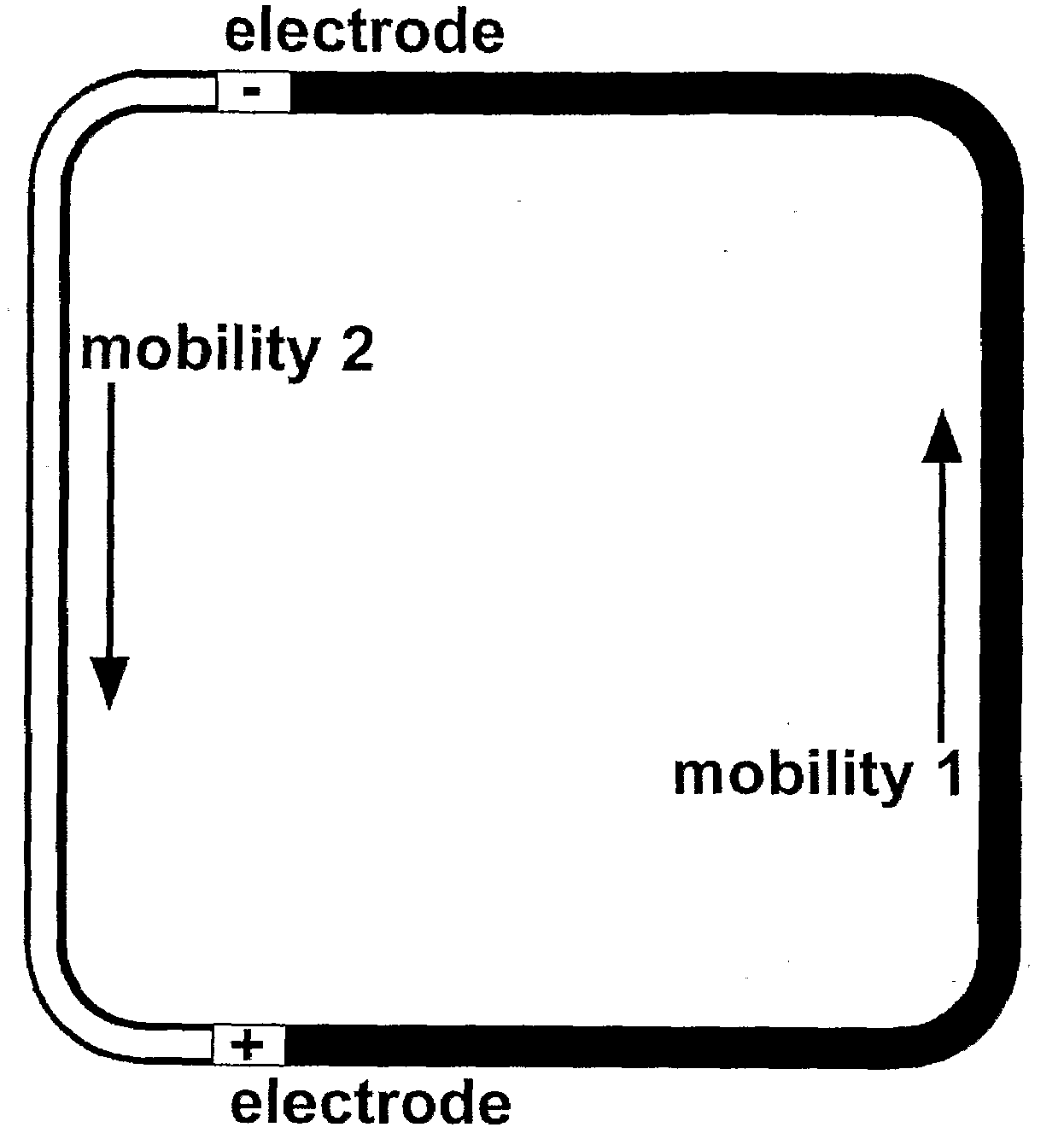
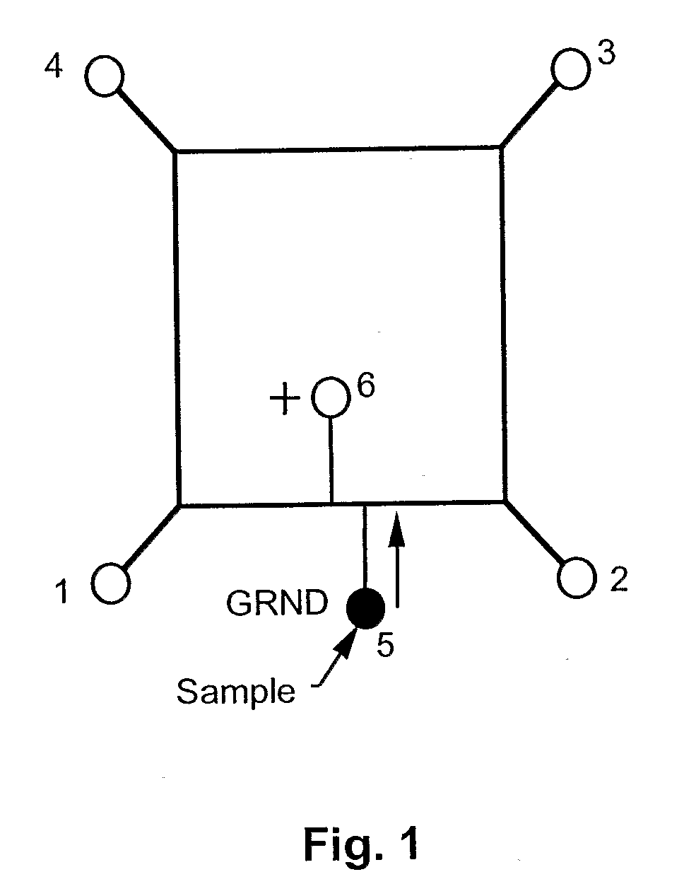
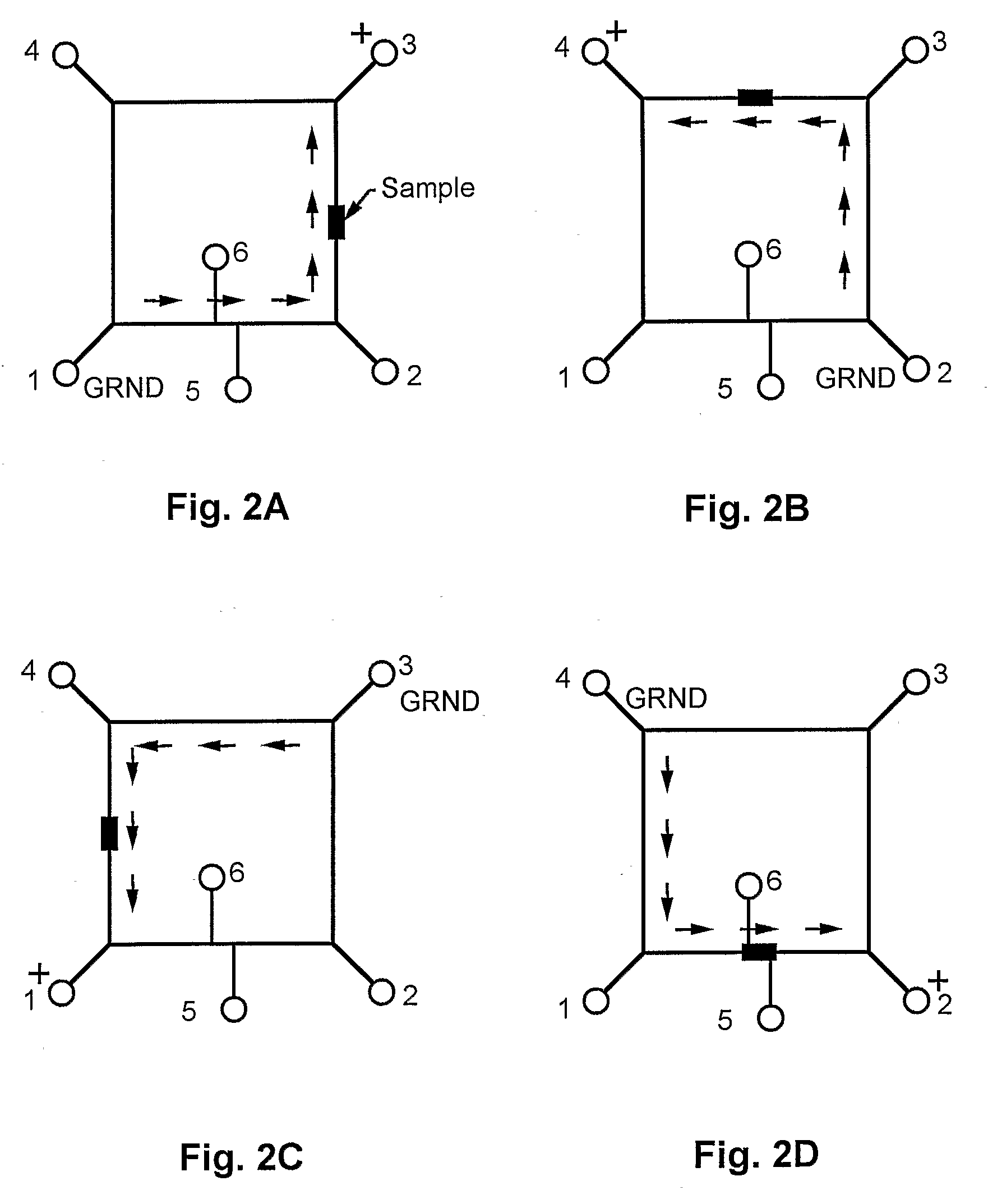
[0050]This prototype embodiment, and the synchronized, cyclic, continuous-flow PCR process are depicted schematically in FIG. 1, and FIGS. 2A through 2D. FIG. 1 depicts sample injection. Reservoirs 1-4 accommodated electrodes for applying voltages between points 1 and 3, as well as between points 2 and 4, for moving the DNA plug through the three temperature zones in a synchronized fashion. A DNA sample was injected into reservoir 5, and a voltage was applied across the electrodes in reservoirs 5 and 6. Sample was moved across the reactor channel to fill the crossed T injector. FIGS. 2A through 2D depict sample cycling. The c...

example 2

[0052]Temperature Control: Each of three temperature zones was heated by a surface-mounted resistor array. Temperatures were monitored by four K-type thermocouples embedded within each array, close to the contact surface between the heater and the chip. Zone temperatures were maintained within 0.5° C. by a PID type control loop. To maintain as uniform a temperature as possible, and to reduce heat transfer between zones, each heater was isolated by an air gap from neighboring heaters. Because some heat transfer is inevitable, the resistance of the end resistor of any zone that is adjacent to a higher temperature zone may be increased to reduce some of its heat generation. By moving the sample through independent temperature zones, the time delay due to temperature ramping is greatly reduced. The delay, therefore, depends principally on the sample migration time from zone to zone, and heat transfer to or from each zone. The surface-mounted heaters were sealed onto a separate polycarbo...

examples 3 and 4

[0053]Surface Modification of PC Microchannels: Various surface modification techniques otherwise known in the art may be used; the surface modifications should be stable in the temperature range of interest, e.g., that used for typical PCR or LDR reactions.

[0054]One approach employed a dynamic coating to modify the microchannel walls to alter the magnitude and direction of electroosmotic flow (EOF). A principal goal is that the EOF should not oppose the electrophoresis of charged species, e.g., DNA. For example, EQF for unmodified polycarbonate (PC) is positive. It is desirable to reverse the direction of the EOF for DNA, because the direction of electrophoresis for DNA is negative. The voltage needed to move DNA through the channels is reduced, and dispersion of the DNA plug due to counter-propagating flows of buffer and DNA is also reduced.

[0055]Hexadimethrine bromide (Polybrene, PB) was used as a dynamic coating material. The channel was first rinsed with 0.1 M NaOH and deionize...


PUM

PropertyMeasurementUnit
temperaturesaaaaaaaaaa

Abstract

Microfluidic devices are disclosed for carrying out cyclic or iterated reactions such as PCR, LDR, and other cyclic or iterated reactions. A microchannel forms a closed loop, through which a reaction mixture may be thermally cycled an arbitrary number of times. Flow is preferably mediated primarily by electrokinetics. Multiple temperature zones may be employed along the course of a single microchannel loop, for example for PCR. Embodiments may be compact, automated, fast, and operable in continuous-flow mode. Real-time reaction monitoring may optionally be used.

Description

[0001](In countries other than the United States:) The benefit of the 17 Oct. 2005 filing date of U.S. patent application 60 / 727,697 is claimed under applicable treaties and conventions. (In the United States:) The benefit of the 17 Oct. 2005 filing date of provisional patent application 60 / 727,697 is claimed under 35 U.S.C. § 119(e).[0002]The development of this invention was partially funded by the United States Government under grants R01-EB002115 and R01-HG01499 awarded by the National Institutes of Health, and grant EPS-0346411 awarded by the National Science Foundation. The United States Government has certain rights in this invention.TECHNICAL FIELD[0003]This invention pertains to thermal cyclers and reactors, particularly to microscale thermal cyclers and reactors, and to other microscale cyclers.BACKGROUND ART[0004]A major scientific advance useful in biological, biochemical, bioterrorism defense, and forensic applications has been the application of microfluidic devices to...

Claims


Application Information

Patent Timeline
Patent Type & Authority Applications(United States)
IPC IPC(8): C12M1/02B01J19/00G01N21/00
CPCB01L3/5027B01L7/525B01L2300/0816B01L2400/0418B01L2300/1827B01L2300/1883B01L2300/0861
Inventor SOPER, STEVEN A.NIKITOPOULOS, DIMITRIS E.MURPHY, MICHAEL C.
Owner BOARD OF SUPERVISORS OF LOUISIANA STATE UNIV & AGRI & MECHANICAL COLLEGE
Why Eureka
Try Eureka