Temperature programmed low thermal mass fast liquid chromatography analysis system

a liquid chromatography and low thermal mass technology, applied in the field of liquid chromatography systems, can solve the problems of increasing the back pressure of the column, increasing the performance of the pumping system, and limiting the application of the system, so as to reduce the power consumption of the lc analysis system, and improve the efficiency of the system.

Inactive Publication Date: 2009-07-09
AGILENT TECH INC
View PDF11 Cites 45 Cited by
  • Summary
  • Abstract
  • Description
  • Claims
  • Application Information

AI Technical Summary

Benefits of technology

[0039]Through the combination of a miniature capillary LC column in close contact with the heating wire and temperature sensing mechanism, which are also in axial alignment with the LC capillary column, and the optimal relationship between the elements

Problems solved by technology

Although small particle sizes offer increased resolution in the LC system, they unfortunately can lead to significantly higher column back pressures, thus increasing demand on the performance of the pumping systems.
Despite benefits associated with operating the LC systems at higher temperatures, the elevated temperature may introduce constraints that may be counter productive.
An important problem is directed to the thermal stability of the column packing chemistry against highly aqueous or buffer containing mobile phases.
Precise temperature control and the generation of thermal gradients in the LC column bed are additional issues at higher temperature operation.
Due to increased flow in the center of the packed bed compared to the walls, the entry into the mobile phase at a different temperature may produce non-uniform temperature distributions across the column bed and reduce resolution.
The steel columns associated with narrow bore LC columns exaggerate the problem by moving the fluid in the center of a tube at a much faster velocity, thus reducing the effective residenc

Method used


Image

  • Temperature programmed low thermal mass fast liquid chromatography analysis system
  • Temperature programmed low thermal mass fast liquid chromatography analysis system
  • Temperature programmed low thermal mass fast liquid chromatography analysis system

Examples


Embodiment Construction

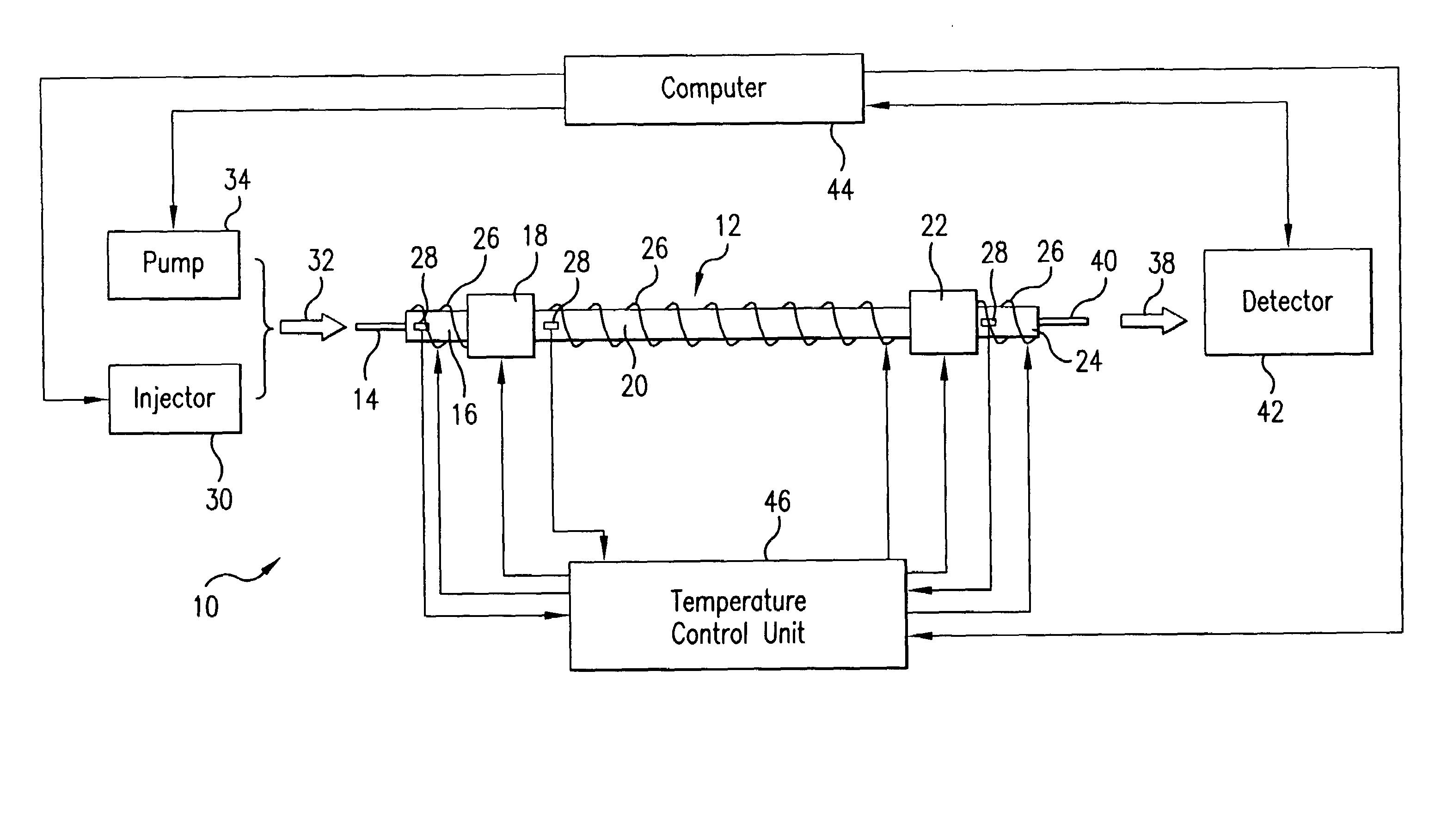
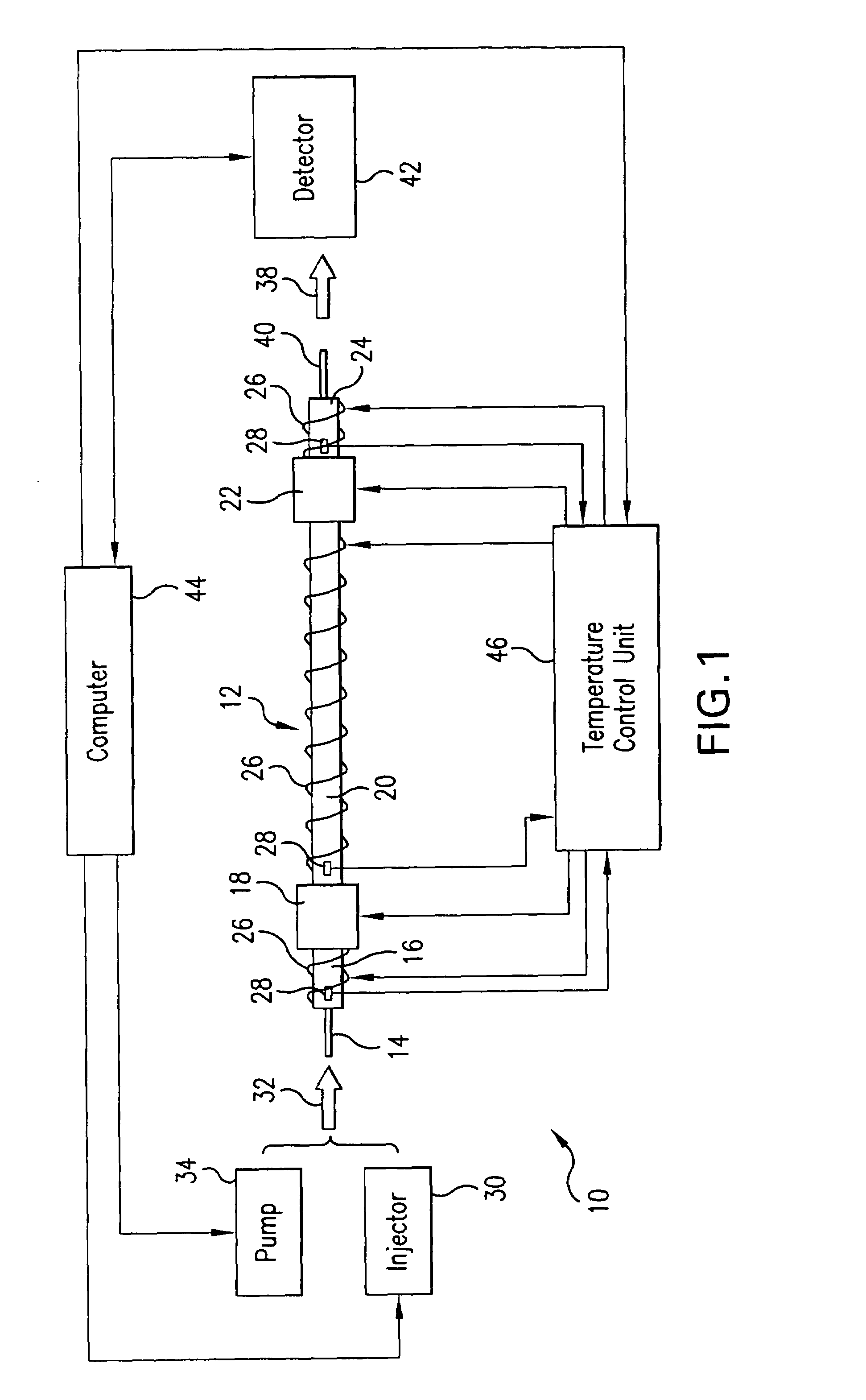
[0059]Referring to FIG. 1, there is shown a temperature programmed low thermal mass liquid chromatography analysis system 10 including an LC column 12 having an inlet end coupled to an LC guard column 14 which is a section of a chromatography tubing inserted into a wire heated tube (transfer line) 16 followed by junction 18 to the LC column 12 contained within a wire heated conduit (or tube) 20. The LC column 12 also has an output end coupled to a junction 22 followed by a wire heated tube 24 (an additional transfer line).

[0060]The junctions 18 and 22 include chromatography fittings that are heated by a small heating block of material, such as aluminum, with a heating cartridge and temperature sensor. Each tube 16 and 24 is formed of a thin walled metal, such as for example aluminum or stainless steel. Aluminum may be preferred for short lengths tubing because of its high thermal conductivity and its ability to bring heat very effectively to its end edges to avoid cold spots at junc...


PUM


Abstract

A temperature programmed low thermal mass fast liquid chromatography system capable of high throughput and low power consumption includes a straight or curved short reloadable low-mass tubular heater with a capillary column extending inside. If the capillary column is long enough, it is coiled to form a coiled capillary LC column (the length of which does not exceed 0.2 m-1.0 m) packed in a singular module package with a heating wire and a temperature sensing wire extending along and in proximity to the LC capillary column. A tubular heater, e.g. a steel tubing, incorporates the LC capillary column, along with the heating wire and the temperatures sensor and is coiled to form a miniature power saving LC module which may be attached outside a chromatography oven. Capillary lengths extend inside the oven between the inlet and outlet of the LC column module and mobile phase source and detector, respectively. An electronic temperature control block is positioned outside the oven cavity and controls the heating of the capillary LC column, as well as other heated zones in the system.

Description

FIELD OF THE INVENTION[0001]The present invention relates to liquid chromatography (LC) systems for analysis of chemical samples. In particular, the subject invention is directed to liquid chromatography analysis systems capable of high speed heating and cooling for the accelerated detection of compounds in a chemical sample and their analysis enhanced by the application of programmed temperature profiles to LC columns.[0002]Moreover, the present system relates to liquid chromatographic column modules for temperature programmed analysis which may be removably integrated with a chromatography oven external to the oven cavity for efficient liquid chromatography analysis.[0003]The present invention is also related to a miniature modular liquid chromatography system which includes a short capillary liquid chromatography column replaceably received within a stainless steel tube along with temperature sensing and heating mechanisms, which altogether are straight, or coiled to form a loope...

Claims


Application Information

Patent Timeline
IPC IPC(8): G01N30/02
CPCG01N30/30G01N2030/3053G01N2030/3007G01N2030/3076
Inventor PURSCH, MATTHIASECKERLE, PATRICLUONG, JIMCORTES, HERNANGRAS, RONDAHOOL, KEVINMUSTACICH, ROBERT
Owner AGILENT TECH INC
Why Eureka
Try Eureka