One piece liquid injection spray cylinder/nozzle

a spray cylinder and liquid injection technology, applied in the field of liquid injection, can solve the problems of increasing cost, limiting the surface treatment available, and high cost of sealing welding in the nozzl

Inactive Publication Date: 2009-07-09
BAUER CHARLES GUSTAV
View PDF10 Cites 25 Cited by
  • Summary
  • Abstract
  • Description
  • Claims
  • Application Information

AI Technical Summary

Problems solved by technology

A hole with a length above the 1:3 ratio is considered a “deep hole” and causes increased cost.
The brazing in of the nozzles limits the surface treatments available to harden the internal cylinder bore, where the piston rings slide.
Seal welding in the nozzles is expensive and forms high stress points where cracking can begin at high operating temperatures.
The cone spray pattern at the top of the spray cylinder can throw liquid against the hot vapor pipe

Method used


Image

  • One piece liquid injection spray cylinder/nozzle
  • One piece liquid injection spray cylinder/nozzle
  • One piece liquid injection spray cylinder/nozzle

Examples


Embodiment Construction

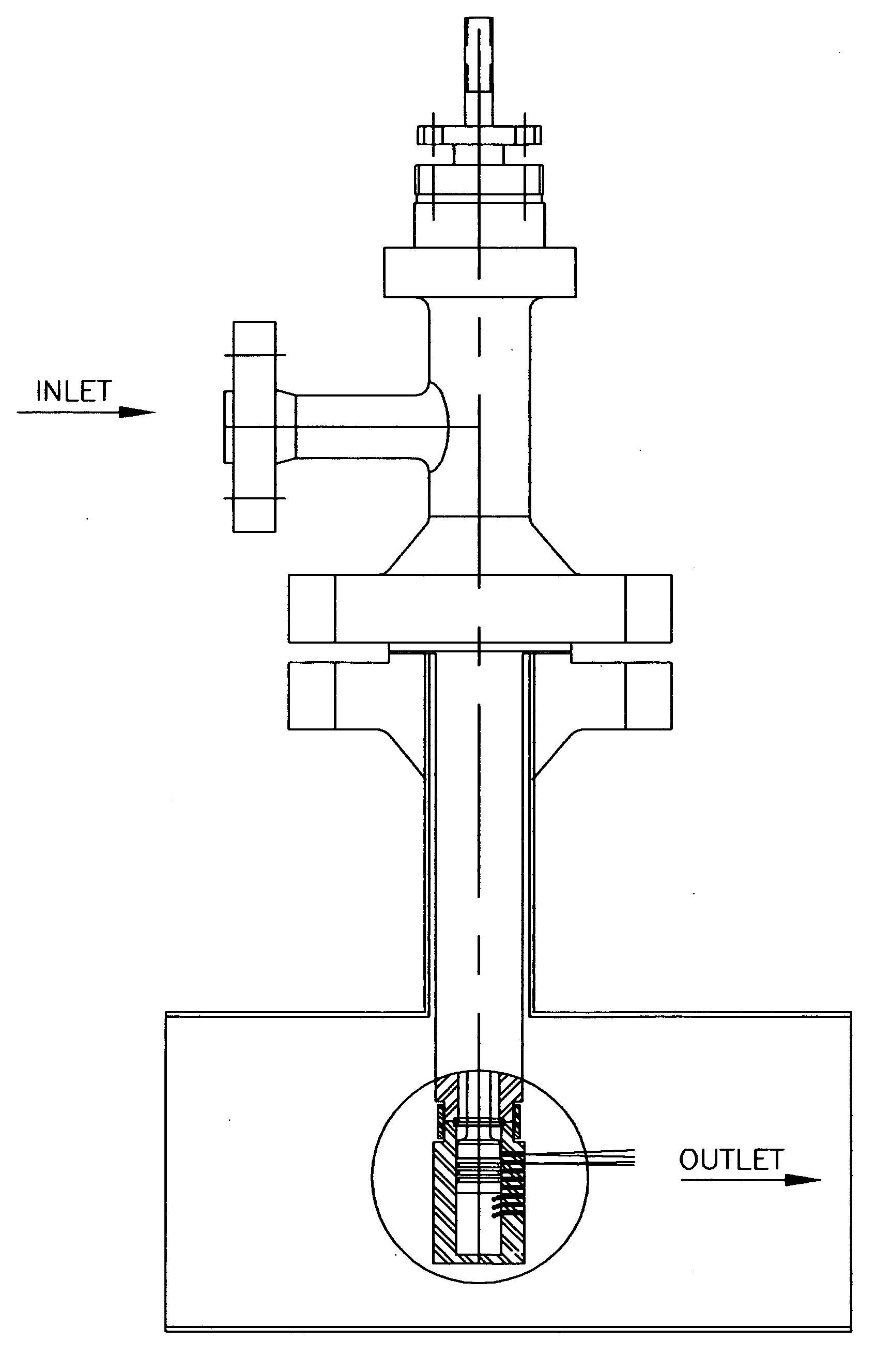
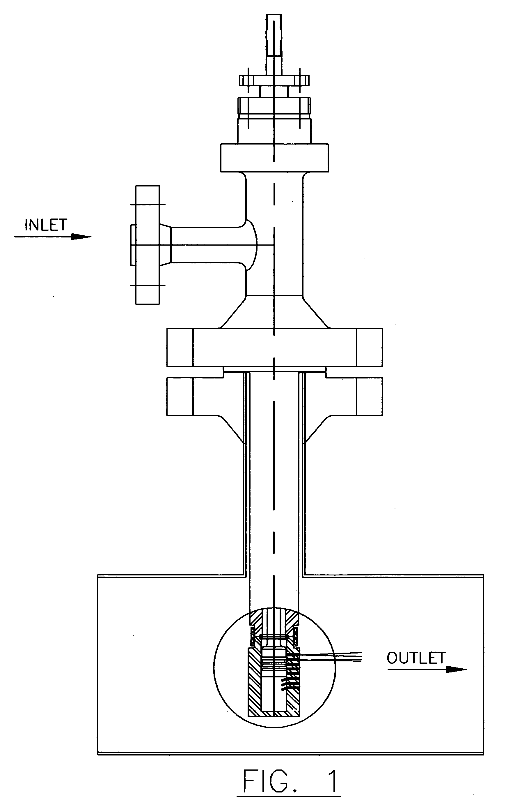
[0006]In light of the aforementioned problems, it is the object of my invention to make a one piece spray cylinder with the nozzles machined directly into it using deep hole drilling technology (below 1:3 diameter to length ratio) and with or without face modifications on the nozzles' outlet side only to form the spray patterning to reduce the liquid droplets to a useable and controllable size.

[0007]The nozzle holes can be made using gun drilling, twist drill or any other method that produces a smooth straight hole into the cylinder. The inside of the cylinder is honed smooth for the piston rings to slide in. The plurality of the holes and the holes' diameter is determined by the quantity of liquid flow required and the opening characteristics desired of the valve. The opening characteristics can be, but not limited to, equal percentage, linier, quick opening and others. The first nozzle is located to give a dead ban, allowing the seat to open before the piston ring allows the liqui...


PUM

PropertyMeasurementUnit
Temperatureaaaaaaaaaa
Pressureaaaaaaaaaa
Flow rateaaaaaaaaaa

Abstract

A one piece spray cylinder/nozzle, with integrally machined nozzles, for use on a high pressure and temperature, probe style, variable nozzle, gas and steam coolers. The nozzle holes can be made by deep drilling techniques such as laser, gun drilling and others methods that produce a hole, with a diameter to depth ratio of less than 1:3. No separately machined nozzles are used. On the outlet end of the nozzle (on the outside of the cylinder only), there are surface machining treatments to produce small, controllable liquid droplets that vaporize quickly into the gas or vapor stream. The spray cylinder bore can be coated, lined or hard faced to resist the ware of the piston rings sliding in it without adding stresses to the spray cylinder body at braze and weld joints. The flow and patterns and valve characteristics can be modified.

Description

BACKGROUND OF INVENTION AND RELATED ARTS STATEMENT[0001]1. Field of Invention[0002]The present invention relates to the field of liquid injection into a vapor or gas stream pipe for the purpose of cooling the stream. More particularly, to control valves for steam and gas coolers of the insertion probe style, with their variable opening nozzle spray cylinder that have mounted on them pneumatic, electric or hydraulic actuator and positioner.[0003]2. Background of Invention[0004]Various designs have been produced similar to the Brand U.S. Pat. No. 4,130,611 using multiple separate nozzles mounted in a pre-machined cylinder by brazing or seal welding. They had to be made this way for two reasons: To shorten the length of the small diameter feeder ports to below a diameter to length 1:3 ratio. This ratio is the standard drilling capability. A hole with a length above the 1:3 ratio is considered a “deep hole” and causes increased cost. The nozzles were of the centripetal type, using a pre...

Claims


Application Information

Patent Timeline
IPC IPC(8): B01D47/00B01F3/04
CPCB01F5/045F22G5/123B01F5/0463B01F25/31331B01F25/313
Inventor BAUER, CHARLES GUSTAV
Owner BAUER CHARLES GUSTAV
Why Eureka
Try Eureka