Vaporization apparatus with precise powder metering

Active Publication Date: 2009-07-09
GLOBAL OLED TECH
View PDF42 Cites 23 Cited by
  • Summary
  • Abstract
  • Description
  • Claims
  • Application Information

AI Technical Summary

Problems solved by technology

It is well known that precisely metering small amounts of powdered materials is difficult.
The use of any sort of additive increases the material transport complexity, for the carrier or additive needs to be added, removed and handled separately from the actual material of interest.
The use of carriers also increases the risk of contamination, which is particularly detrimental in the pharmaceutical and electronics manufacturing industries where there is a particular need to meter materials.
Transporting a mixture that is mostly inert carrier adds costs and complexities to the system, and increases the potential for the introduction of contaminates into the material feed.
One of the problems with using this type of auger structure with powders is varying discharge rate.
Using the auger in a vertical orientation such that the powder is evenly distributed around the interior of the auger barrel can attenuate the cyclic discharge, but the cyclical variation remains and the mechanical drive arrangement for the auger and agitator is more complicated.
The organic materials used in the manufacture of OLED devices are often subject to degradation when maintained at or near the desired rate-dependent vaporization temperature for extended periods of time.
Exposure of sensitive organic materials to higher temperatures can cause changes in the structure of the molecules and associated changes in material properties.
In this manner, the material is c

Method used


Image

  • Vaporization apparatus with precise powder metering
  • Vaporization apparatus with precise powder metering
  • Vaporization apparatus with precise powder metering

Examples


Embodiment Construction

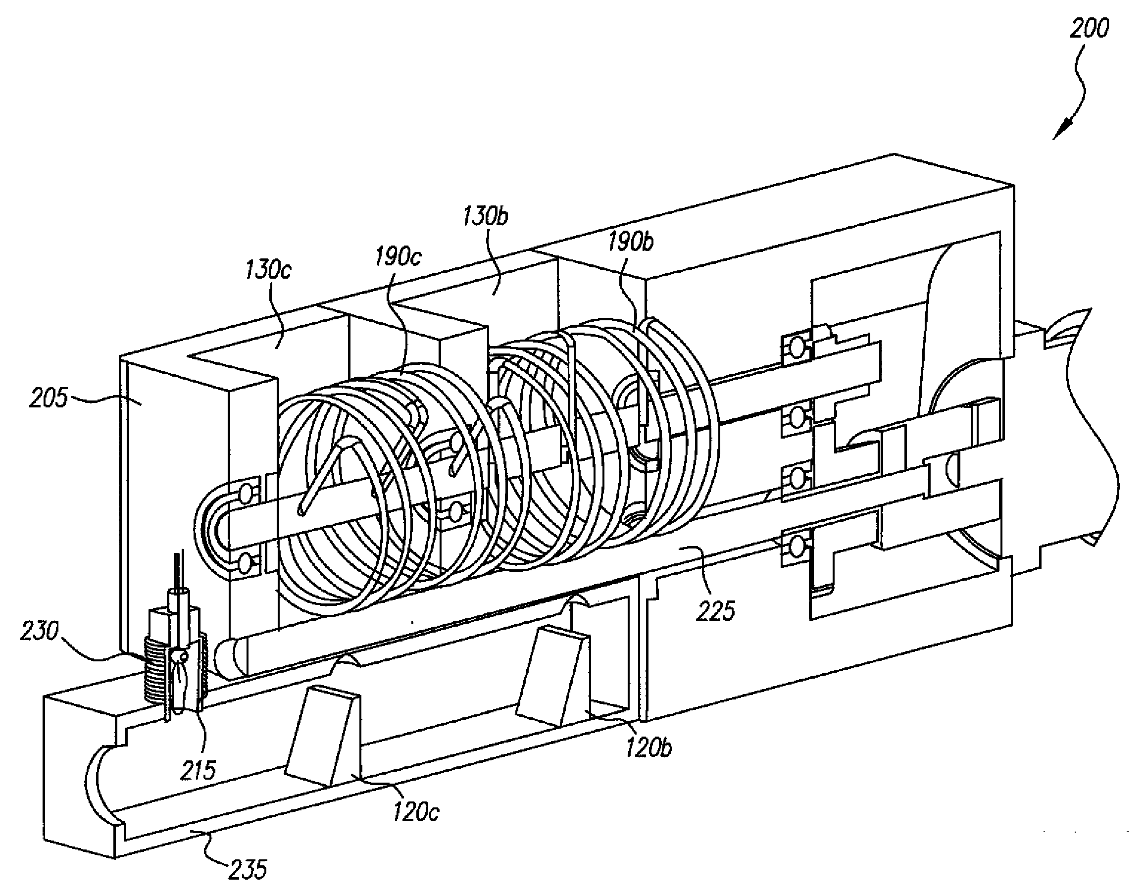
[0038]Turning now to FIG. 3, there is shown a cutaway view of one embodiment of an apparatus according to the present invention. Vaporizing apparatus 100 is an apparatus for vaporizing particulate material. Vaporizing apparatus 100 includes a metering apparatus, which includes: a reservoir for receiving particulate material; a housing having an internal volume and first and second openings; a rotatable shaft disposed in the internal volume having a shape corresponding to that of the internal volume and a circumferential groove; and a scraper having at its end substantially the same cross section as the groove in the rotating shaft. These components will be described in more detail. Reservoir 130a is for receiving particulate material. The particulate material can include a single component, or can include two or more different material components, each one having a different vaporization temperature. Although not shown, reservoir 130a can include a larger storage and feeding apparat...


PUM

PropertyMeasurementUnit
Widthaaaaaaaaaa
Depthaaaaaaaaaa
Volumeaaaaaaaaaa

Abstract

Apparatus for vaporizing a particulate material, comprising a metering apparatus including: a reservoir; a housing having an internal volume and first and second openings for respectively receiving and discharging the particulate material; a rotatable shaft disposed in the internal volume, the shaft having a smooth surface and a circumferential groove for receiving particulate material from the reservoir and for discharging the particulate material; the rotatable shaft and the internal volume cooperating such that the particulate material is transported by the circumferential groove and not along the remainder of the rotatable shaft; a scraper disposed in relation to the second opening, having at its end substantially the same cross section as the groove in the rotating shaft, the scraper cooperating with the groove to dislodge particulate material retained therein, and in response to the shaft rotating, delivers metered amounts of particulate material through the second opening; to the flash evaporator.

Description

FIELD OF THE INVENTION[0001]The present invention relates to metering of powdered materials, over a large range of feed rates, into a vaporization apparatus.BACKGROUND OF THE INVENTION[0002]There is a need to be able to accurately and precisely continuously meter small quantities of powdered materials, for example 1 to 9 micrograms per second. The electronics industry has a need to meter small quantities of powdered materials to a vaporization zone for direct vapor deposition or for precursors in chemical vapor deposition (CVD). There is also a need to be able to accurately and precisely meter material amounts three orders of magnitude higher, for example 1000 micrograms per second. In many systems, it would be advantageous to be able to meter powdered materials over the range of 1 to 1000 micrograms with the same equipment. Organic light emitting diode devices (OLEDs), for instance have a light emitting layer that often contains a host and a dopant that are deposited in amounts dif...

Claims


Application Information

Patent Timeline
IPC IPC(8): C23C16/448C23C16/54
CPCC23C16/4486C23C14/246
Inventor LONG, MICHAELPALONE, THOMAS W.KOPPE, BURCE E.BOROSON, MICHAEL L.
Owner GLOBAL OLED TECH
Why Eureka
Try Eureka