Ceramic Component With Surface Resistant To Hot Gas and Method for the Production Thereof

Inactive Publication Date: 2009-07-16
SIEMENS AG
View PDF19 Cites 10 Cited by
  • Summary
  • Abstract
  • Description
  • Claims
  • Application Information

AI Technical Summary

Benefits of technology

[0015]As already described previously in relation to the inventive ceramic component, the poorly reactive coating increases the resistance properties of the ceramic component equipped with it. For

Problems solved by technology

As well as thermal and mechanical stresses the heat shield elements are also exposed to heavily corrosive stresses as a result of the flow of hot gas.
The corrosive loads can result in a loss of material on the heat shield element which reduces its lifetime.
This loss of material is attributable to a combination of c

Method used


Image

  • Ceramic Component With Surface Resistant To Hot Gas and Method for the Production Thereof
  • Ceramic Component With Surface Resistant To Hot Gas and Method for the Production Thereof
  • Ceramic Component With Surface Resistant To Hot Gas and Method for the Production Thereof

Examples


Embodiment Construction

[0024]The invention is described below with reference to a ceramic heat shield element for constructing a ceramic heat shield on the wall of a gas turbine combustion chamber.

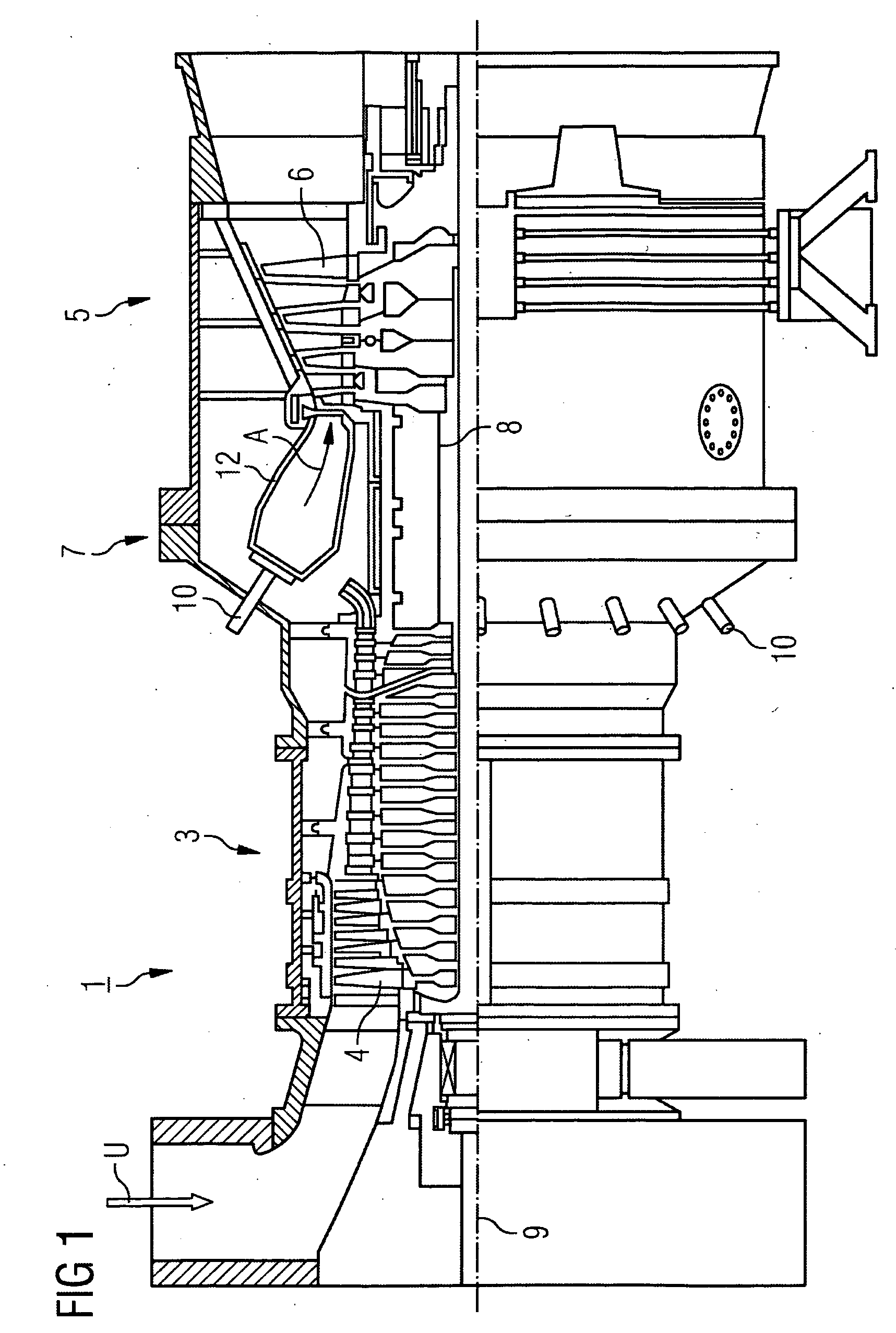
[0025]A gas turbine installation 1 comprises a compressor section 3, a turbine section and a burner section 7. In the compressor section 3 and in the turbine section 5 compressor blades 4 or turbine blades 6 are arranged on common shaft 8 which is also referred to as the turbine rotor. The turbine rotor 8 is supported to allow rotation around a central axis 9.

[0026]The burner section comprises a numbers of burners 10 which come out into a combustion chamber 12 which in its turn comes out into the turbine section 5. In the present exemplary embodiment the combustion chamber 12 is embodied as an annular combustion chamber, i.e. it extends in a ring around the turbine rotor, and is lined with a ceramic heat shield.

[0027]During operation of the gas turbine installation 1 surrounding air U is sucked in via the compre...


PUM

PropertyMeasurementUnit
Percent by massaaaaaaaaaa

Abstract

The invention relates to a ceramic component comprising a surface which is resistant to hot gas, and a method for the production thereof. Said ceramic component comprises a ceramic body and a surface which is resistant to hot gas. According to the invention, the surface which is resistant to hot gas is provided with a poorly reactive mineral coating.

Description

CROSS REFERENCE TO RELATED APPLICATIONS[0001]This application is the US National Stage of International Application No. PCT / EP2006 / 063754, filed Jun. 30, 2006 and claims the benefit thereof. The International Application claims the benefits of European application No. 05014473.2 filed Jul. 4, 2005, both of the applications are incorporated by reference herein in their entirety.FIELD OF INVENTION[0002]The present invention relates to a ceramic component with surface resistant to hot gas and method for the production thereof. In addition the present invention relates to a combustion space, especially a gas turbine combustion chamber.BACKGROUND OF THE INVENTION[0003]The walls of combustion spaces which conduct hot gases such as those of the combustion chambers of gas turbine installations required a thermal shielding of the supporting wall structure against attack by the hot gases. The thermal shielding can for example be implemented by a lining resistant to hot gases placed in front o...

Claims


Application Information

Patent Timeline
IPC IPC(8): B32B9/04B05D3/02B05D3/12
CPCF23M5/00F23R3/007F23M2900/05004C04B41/87C04B41/009C04B41/5031C04B41/5042C04B41/5046C04B35/10C04B35/185C04B41/4539C04B41/455C04B41/4527
Inventor GROTE, HOLGER
Owner SIEMENS AG
Why Eureka
Try Eureka