Process of preparing continuous filament composed of nanofibers

a nanofiber and nanofiber technology, applied in the field of preparing a continuous filament or yarn, can solve the problems of inability to make fibers with a diameter less than 1,000 nm by using the above two methods, uneven dyeing, and complex artificial leather making process

Inactive Publication Date: 2009-07-30
FINETEX TECH GLOBAL +1
View PDF14 Cites 50 Cited by
  • Summary
  • Abstract
  • Description
  • Claims
  • Application Information

AI Technical Summary

Benefits of technology

[0130]The present invention is capable of making a continuous filament consisting of nanofibers by a simpler continuous process. The continuous filament made according to the present invention is improved much in physical property and thus useful as mate

Problems solved by technology

Nevertheless, it is impossible to make fibers with a diameter less than 1,000 nm by using the above two methods.
Meanwhile, in the case of the split type conjugated spinning, two polymer components (for example, polyester and polyamide) different in dyeing property coexist in fibers, thus dyeing unevenness is produced and an artificial leather making process becomes complicated.
Besides, it is difficult to make fibers with a diameter less than 2,000 nm by using the above method.
As seen from above, the prior art electrospinning method is only capable of making a web and n

Method used


Image

  • Process of preparing continuous filament composed of nanofibers
  • Process of preparing continuous filament composed of nanofibers
  • Process of preparing continuous filament composed of nanofibers

Examples


example 1

[0132]Poly(ε-caprolacton) polymer (manufactured by Aldrich, USA) with a number average molecular weight of 80,000 was dissolved in a mixed solvent of methylene chloride / N,N-dimethylformamide (volume ratio: 75 / 25) at a concentration of 13% by weight, to thereby obtain a polymer spinning liquid.

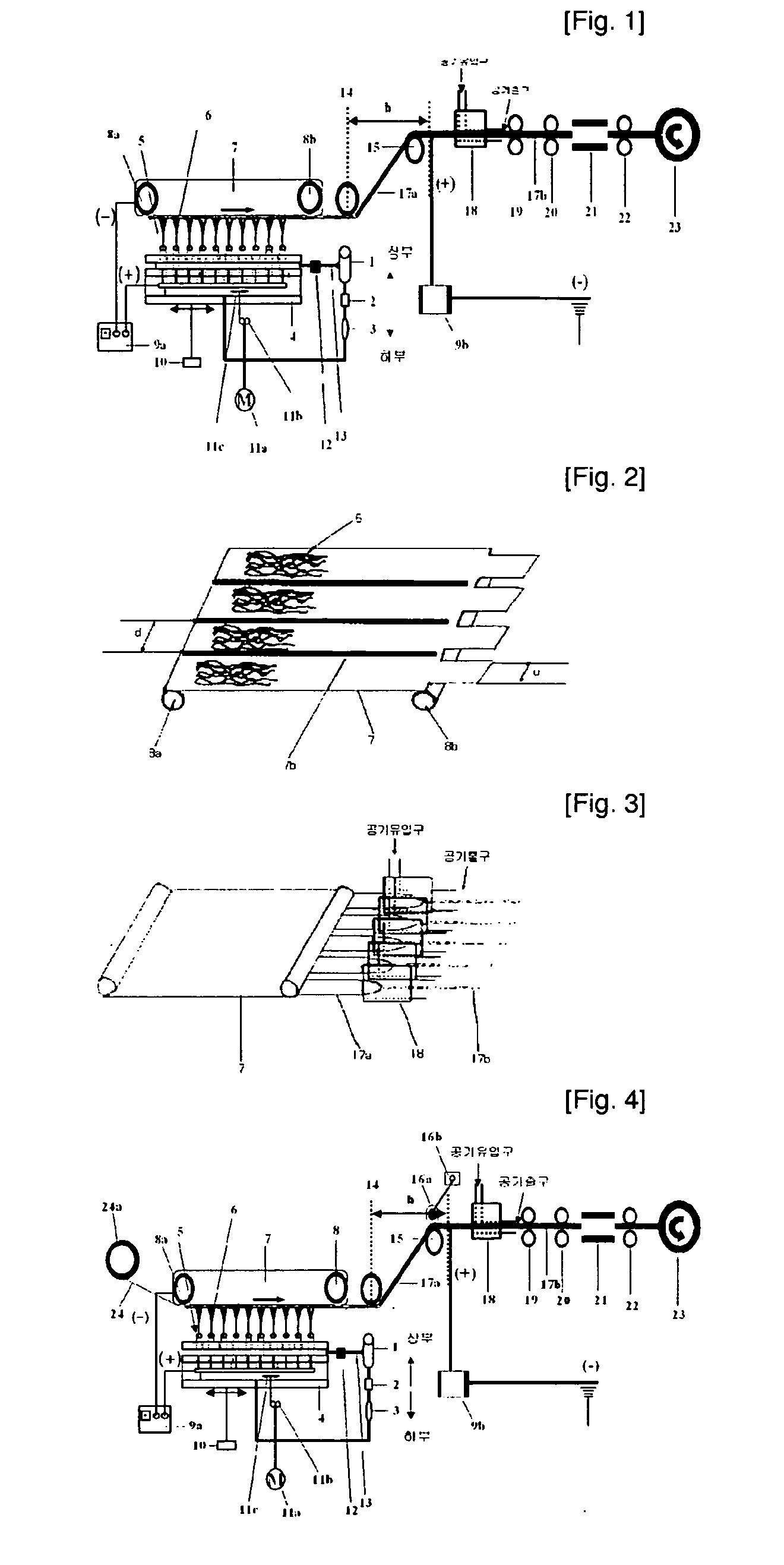
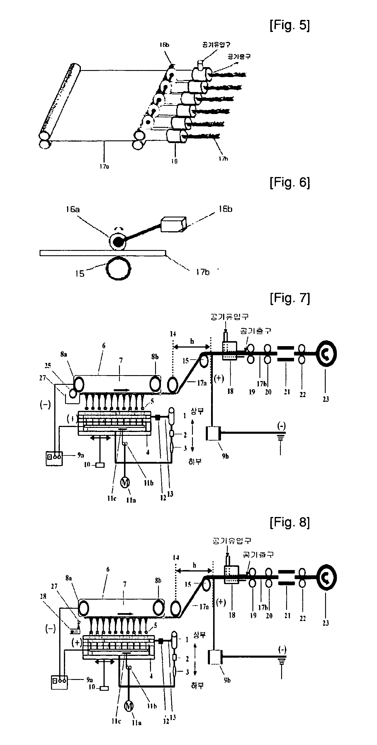
[0133]The surface tension of the polymer spinning liquid was 35 mN / m, the solution viscosity was 250 centipoises under a room temperature, the electric conductivity was 0.02 mS / m and permittivity constant was 90. The polymer spinning liquid was electrostatically spun to a collector 7 located on the top part through a nozzle block 4, with nozzles having a 1 mm diameter arranged thereto in a row, via a metering pump 2 as shown in FIG. 1, thereby making a nanofiber web with a unit width of 2.5 cm. At this time, as the nozzle block 4, used was a nozzle block which consists of ten unit nozzle blocks each having 80 nozzles arranged thereto in a row in a traveling direction of nanofibers and which has...

example 2

[0144]Polyurethane resin (manufactured by Daewoo International, Korea) with a number average molecular weight of 80,000 and polyvinyl chloride (LG Chemical, Korea) with a polymerization degree of 800 was dissolved in a mixed solvent of dimethylformamide / tetrahydrofuran (volume ratio: 5 / 5) at a weight ratio of 70 / 30, to thereby obtain a 12.5% by weight polymer spinning liquid. The viscosity of the spinning liquid was 450 centipoises.

[0145]The polymer spinning liquid was electrostatically spun to a collector 7 located on the top part through a nozzle block 4, with 400 nozzles having a 1 mm diameter diagonally arranged thereto, via a metering pump 2 as shown in FIG. 4, thereby making a wide nanofiber web with a 60 cm width.

[0146]At this time, the throughput rate per nozzle was 2.0 mg / min. In electrospinning, the nozzle block 4 was bilaterally reciprocated at a velocity of 2.5 m / min by using a nozzle block bilateral reciprocating device 10, and the collector 7 was heated at 85° C.

[0147]...

example 3

[0155]Nylon 6 resin having a relative viscosity of 3.2 was dissolved in formic acid at a concentration of 15% by weight to prepare a spinning liquid. The surface tension of the polymer spinning liquid was 49 mN / m, the solution viscosity was 1,150 centipoises under a room temperature, and the electric conductivity was 420 mS / m.

[0156]The polymer spinning liquid was electrostatically spun to a collector 7 located on the top part through a nozzle block 4, with nozzles having a 1 mm diameter arranged thereto in a row, via a metering pump 2 as shown in FIG. 1, thereby making a nanofiber web with a unit width of 1.8 cm.

[0157]At this time, as the nozzle block 4, used was a nozzle block which consists of ten unit nozzle blocks each having 100 nozzles arranged thereto in a row in a traveling direction of nanofibers and which has a total of 1000 nozzles. The throughput rate per nozzle was 1.2 mg / min.

[0158]Further, as the collector 7, used was a collector having barriers 7b of Teflon installed ...


PUM

PropertyMeasurementUnit
Widthaaaaaaaaaa
Amphotericaaaaaaaaaa
Velocityaaaaaaaaaa

Abstract

Conventional electrospinning was problematic in that it is incapable of making a continuous filament (yarn) by a simple and continuous process. To solve the above problem, there is provided a method for making a continuous filament consisting of nanofibers according to the present invention, wherein a polymer spinning liquid is electrostatically spun to a collector 7 through nozzles 5 to obtain a nanofiber web 17a of ribbon form, then the nanofiber web 17a is passed through an air twister 18 and twisted to obtain a nanofiber filament 17b of a continuous filament form, and then the nanofiber filament 17b is drawn.

Description

TECHNICAL FIELD[0001]The present invention relates to a process of preparing a continuous filament or yarn (hereinafter, referred to as ‘filament’) composed of nanofibers, and more particularly, to a process of preparing a continuous filament by a continuous process by using electrospinning.[0002]In the present invention, nanofibers indicate fibers having a fiber diameter of less than 1,000 nm, and more preferably, less than 500 nm.[0003]A nonwoven fabric or the like consisting of nanofibers is variously utilizable as artificial leather, filter, diaper, sanitary pad, suture, adhesion preventive agent, wiping cloth, artificial vessel, bone fixture, etc., especially, very useful for the production of artificial leather.BACKGROUND ART[0004]As conventional techniques for making ultrafine fibers or nanofibers suitable to make artificial leather or the like, sea-island type conjugated spinning, split type conjugated spinning, blend spinning and so one are known.[0005]In the case of the se...

Claims


Application Information

Patent Timeline
IPC IPC(8): H05B7/00D01D5/00D01D5/04D01F1/00D01F6/62D01F9/00D02G3/02D02G3/04D02J1/22D04H1/728
CPCD01D5/0076
Inventor KIM, HAK-YONG
Owner FINETEX TECH GLOBAL
Why Eureka
Try Eureka