Orthopedic component of low stiffness

Active Publication Date: 2009-07-30
ZIMMER INC
View PDF31 Cites 139 Cited by
  • Summary
  • Abstract
  • Description
  • Claims
  • Application Information

AI Technical Summary

Benefits of technology

[0011]Attaching a biocompatible polymer to a porous material to form an orthopedic implant allows the polymer to be received within the pores of the material. When the polymer hardens, the interaction of the two materials provides a firm securement between the porous layer and the polymer layer to form the orthopedic component. Additionally, when the biocompatible polymer is compression or injection molded, for example, to the porous material, a locking feature, such a groove configured to receive a corresponding snap ring, for example, may be integrally formed in and/or on the polymer. By integrally forming a locking feature into or on the orthopedic component, the machining steps necessary to finish the orthopedic component may be reduced and/or entirely eliminated.
[0012]Advantageously, by manufacturing an orthopedic component in accordance with embodiments of the present invention, the orthopedic component has a stiffness which is lower than the stiffness of other orthopedic components. As a result, the present invention lessens the effects of stress shielding on the natural bone stock, reducing the potential for osteolysis and bone resorption.
[0013]Additionally, the present invention provides a surgeon with the ability to drill bone screw receiving apertures into the orthopedic component at the most advantageous locations. Thus, when implanting an acetabular shell, for example, the surgeon may identify the a

Problems solved by technology

As result, the bone may begin to undergo atrophy and decalcification resulting in a weaker bone structure.
Further, by utilizing an anti

Method used


Image

  • Orthopedic component of low stiffness
  • Orthopedic component of low stiffness
  • Orthopedic component of low stiffness

Examples


example 1

Effective Stiffness of PEEK Layer / Porous Layer Construct

[0069]An analytical model was used to study the effective stiffness of a layer of PEEK positioned adjacent to a layer of porous metal.

[0070]The effective stiffness of a layer of PEEK positioned adjacent to a layer of porous metal is dependent on both the material properties and geometries of the individual layers. Thus, to attempt to remove any geometric effects, an analytical model was created to include a rectangular PEEK layer positioned atop a corresponding rectangular porous metal layer. The model incorporated frictionless contact between the PEEK layer and porous metal layer and with none of the PEEK penetrating into the pores of the porous metal layer. Additionally, the porous metal layer is assumed to have properties substantially similar to a porous metal layer formed in accordance with Trabecular Metal™ technology, as described in detail above. The model was then subjected to uniaxial compression. The stress is equall...

example 2

Effects of Acetabular Cup Geometry on PEEK Layer / Porous Layer Stiffness

[0074]A Finite Element (FE) model was used to study the effective stiffness of an idealized acetabular hip cup model having a layer of PEEK interdigitated with a layer of porous metal.

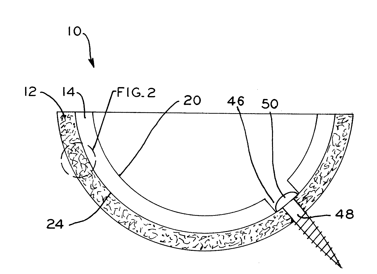
[0075]A 3-D parametric FE model was developed using commercially available FE software ABAQUS 6.7 (ABAQUS, Inc., Providence R.I., USA). The FE model included a femoral component, an acetabular cup, and a bone cement boundary. The femoral component was modeled to be rigid and spherical with a radius, Rfemoral, of 16 mm. The acetabular cup was modeled to have a series of successive layers. The innermost layer is a UHMWPE layer which forms the acetabular liner of the acetabular construct and against which the femoral component articulates. The acetabular shell of the acetabular construct was modeled to have an innermost PEEK layer, an interdigitated PEEK / porous metal layer, and an outermost porous metal layer. The porous metal layer wa...

example 3

Effects of Layer Thickness on a Porous Metal / UHMWPE Orthopedic Component

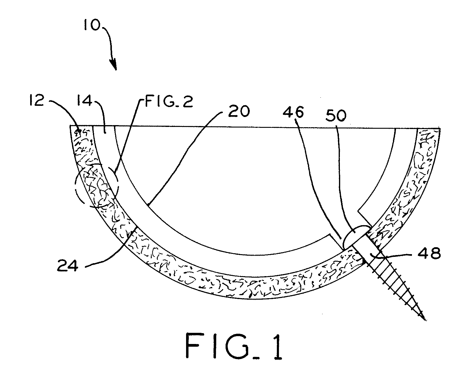
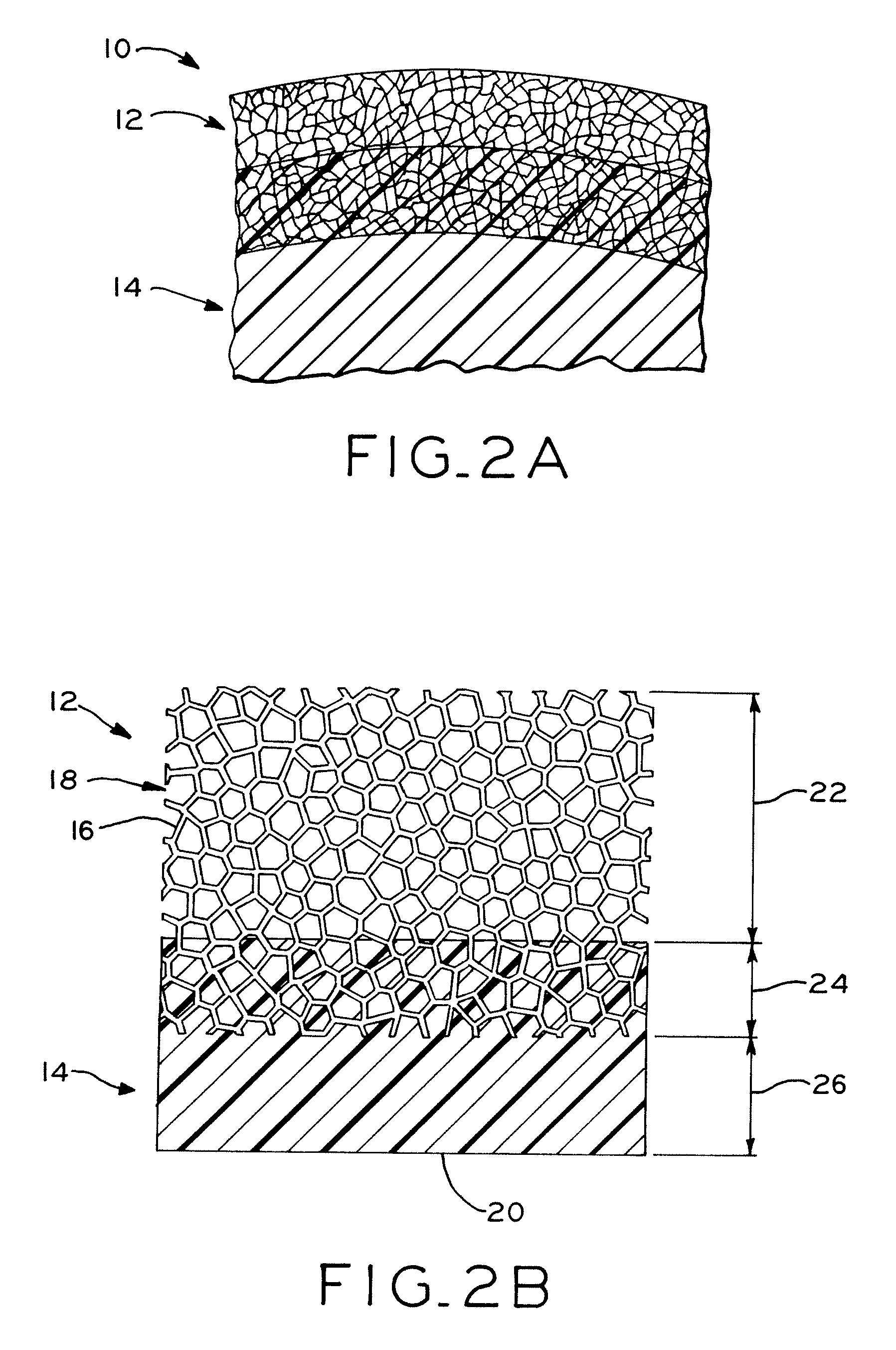
[0080]A 2D stochastic microstructural FE model was developed to represent an idealized acetabular hip cup having a layer of UHMWPE interdigitated with a layer of porous metal. The internal geometry was based on a 2D random Voronoi structure generated by a custom program in FORTRAN. This program also allows changing parametrically the thickness of the three layers, i.e., the UHMWPE layer, the interdigitated layer, and the porous metal layer, to create different designs. Tantalum microstructs, such as those formed in a material created using Trabecular Metal™ technology, are portions of ligaments 16, shown in FIG. 2a, having a loose end and defining the perimeter of the porous metal layer. These tantalum microstructs were modeled as a bilinear elastic material, as shown in FIG. 7, whereas UHMWPE was modeled as a multilinear elastic material, as shown in FIG. 8. Additionally, the various properties of the UHMWPE th...


PUM

PropertyMeasurementUnit
Thicknessaaaaaaaaaa
Thicknessaaaaaaaaaa
Pressureaaaaaaaaaa

Abstract

An orthopedic component having multiple layers that are selected to provide an overall modulus that is substantially lower than the modulus of known orthopedic components to more closely approximate the modulus of the bone into which the orthopedic component is implanted. In one exemplary embodiment, the orthopedic component is an acetabular shell. For example, the acetabular shell may include an outer layer configured for securement to the natural acetabulum of a patient and an inner layer configured to receive an acetabular liner. The head of a femoral prosthesis articulates against the acetabular liner to replicate the function of a natural hip joint. Alternatively, the inner layer of the acetabular shell may act as an integral acetabular liner against which the head of the femoral prosthesis articulates.

Description

CROSS-REFERENCE TO RELATED APPLICATIONS[0001]This application claims the benefit under Title 35 U.S.C. §119(e) of U.S. Provisional Patent Application Ser. No. 61 / 104,870, entitled “ORTHOPEDIC COMPONENT OF LOW STIFFNESS”, filed on Nov. 13, 2008, U.S. Provisional Patent Application Ser. No. 61 / 038,281, entitled “ORTHOPEDIC COMPONENT OF LOW STIFFNESS”, filed on Mar. 20, 2008, U.S. Provisional Patent Application Ser. No. 61 / 024,737, entitled “ACETABULAR COMPONENT”, filed on Jan. 30, 2008, and U.S. Provisional Patent Application Ser. No. 61 / 024,778, entitled “ACETABULAR COMPONENT”, filed on Jan. 30, 2008, the entire disclosures of which are hereby expressly incorporated by reference herein.BACKGROUND[0002]1. Field of the Invention[0003]The present invention relates to orthopedics, and, particularly, to orthopedic implants.[0004]2. Description of the Related Art[0005]During orthopedic surgery, such as a total hip arthroplasty, orthopedic prostheses are implanted into a patient's body. For...

Claims


Application Information

Patent Timeline
IPC IPC(8): A61F2/28A61F2/32B29D31/505B29D35/04
CPCA61B17/86B29C45/14A61F2/34A61F2002/30329A61F2002/305A61F2002/3092A61F2002/3096A61F2002/30981A61F2002/3291A61F2002/3401A61F2002/3411A61F2220/0025A61F2310/00131A61L27/18A61L27/50A61L27/56A61F2/30942B29C43/18B29C70/682C08L71/12A61F2002/30495A61F2/3094C08L71/00
Inventor CASE, KIRT L.POPOOLA, OLUDELE O.KISSLING, ROBBYMIMNAUGH, BRION R.NEWSOME, ARCHIE W.PANCHISON, CLARENCE M.PLETCHER, DIRK L.SCHLEMMER, RANDY L.FANG, ZHIBINVIVANCO, JUANRUFNER, ALICIA
Owner ZIMMER INC
Why Eureka
Try Eureka