Optical fiber amplifier and a control method therefor

a technology of optical fiber amplifier and control method, which is applied in the direction of optical waveguide light guide, optical elements, instruments, etc., can solve the problems of light losing power, information being lost, and further improvement of edfa performance is difficult without increasing the number of amplifier components, so as to achieve the effect of improving performance and significantly reducing the edfa footprin

Active Publication Date: 2009-08-13
LUMENTUM OPERATIONS LLC
View PDF30 Cites 28 Cited by
  • Summary
  • Abstract
  • Description
  • Claims
  • Application Information

AI Technical Summary

Benefits of technology

[0012]In accordance with the present invention, a planar lightwave circuit (PLC) is used as a platform for integration of WDM couplers and taps. The erbium doped fiber (EDF) and pump diode lasers are coupled to the PLC by using a fiber array. A multiport reflective optical isolator and a photodiode array are coupled mechanically and optically to a side of the PLC. Thus, fiber pigtails are eliminated and th

Problems solved by technology

While propagating through an optical fiber, light tends to lose power.
At the same time, a goal of the amplifier is to provide constant gain, which should not depend on the power or wavelength loading condition; otherwise, some channels will not have sufficient power and signal-to-noise level at the receiver end, resulting in info

Method used


Image

  • Optical fiber amplifier and a control method therefor
  • Optical fiber amplifier and a control method therefor
  • Optical fiber amplifier and a control method therefor

Examples


Embodiment Construction

[0053]While the present teachings are described in conjunction with various embodiments and examples, it is not intended that the present teachings be limited to such embodiments. On the contrary, the present teachings encompass various alternatives, modifications and equivalents, as will be appreciated by those of skill in the art.

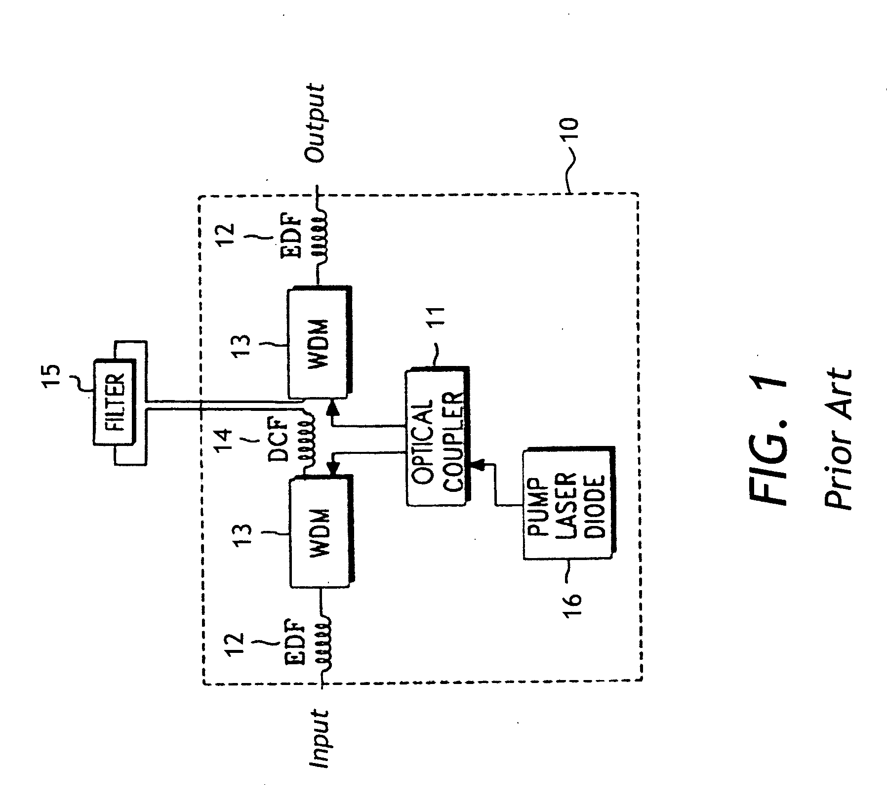
[0054]Referring to FIG. 1, an optical circuit of a prior-art dual-stage erbium doped fiber amplifier (EDFA) 10 is depicted. The EDFA 10 has two erbium-doped fiber (EDF) coils 12 between “Input” and “Output” ports as shown, two wavelength division multiplexing (WDM) couplers 13, a dispersion-compensating fiber 14, a gain flattening filter (GFF) 15, an optical coupler 11, and a pump laser diode 16. The pump light from the pump laser diode is split in two paths, each being coupled through the WDM 13 to a respective EDF coil 12 as shown with arrows in FIG. 1. Using the coupler 11 reduces cost of the amplifier 10 because only one pump laser source 16, and not ...


PUM


Abstract

A fiber amplifier having two erbium doped fiber coils and a pump laser diode optically coupled, through a fiber array, to a planar lightwave circuit, is described. A photodetector array, a multiport free-space optical isolator, and a strip of thin-film gain flattening filter are attached to a side surface of the planar lightwave circuit, which has a tunable optical power splitter for variably splitting the optical pump power for the laser diode between the two erbium doped fiber coils, and variable tilters for correcting the gain tilt of the amplifier. The variable splitter and the tilters are thermally tunable Mach-Zehnder interferometers.

Description

CROSS-REFERENCE TO RELATED APPLICATIONS[0001]The present invention claims priority from U.S. Patent Application No. 61 / 028,429 filed Feb. 13, 2008, entitled “Novel Components In Relation To PLC Amplifier”, by Bolshtyansky et al., which is incorporated herein by reference for all purposes.TECHNICAL FIELD[0002]The present invention relates to optical fiber amplifiers, and in particular to erbium doped fiber amplifiers used in optical transmission systems, and methods of control of such amplifiers.BACKGROUND OF THE INVENTION[0003]In a wavelength division multiplexing (WDM) optical transmission system, optical signals at a plurality of wavelengths are encoded with digital streams of information. These encoded optical signals, or optical channels, are combined together and transmitted through a series of spans of an optical fiber comprising a transmission link of a WDM fiberoptic network. At a receiver end of the transmission link, the optical channels are separated, whereby each optical...

Claims


Application Information

Patent Timeline
IPC IPC(8): H01S3/0941
CPCH01S3/06754H01S3/06758H01S2301/04H01S3/2383H01S3/1305
Inventor BOLSHTYANSKY, MAXIMCOWLE, GREGORYKEYWORTH, BARRIEROORDA, PETER DAVID
Owner LUMENTUM OPERATIONS LLC
Why Eureka
Try Eureka