
Electromagnetic shielding light-transmitting member and method for manufacturing same

a technology of electromagnetic shielding and light-transmitting components, which is applied in the manufacture of electrode systems, electric discharge tubes/lamps, instruments, etc., can solve the problems of weaker electromagnetic waves compared with other displays, microwave may have a harmful influence on the human body, and the effect of reducing the adhesive quality, improving product yield and excellent quality

Inactive Publication Date: 2009-08-20
TOPPAN PRINTING CO LTD
View PDF2 Cites 9 Cited by
  • Summary
  • Abstract
  • Description
  • Claims
  • Application Information

AI Technical Summary

Benefits of technology

[0039]In the invention, scratching and foreign matters do not remain in an electromagnetic wave shielding light-transmitting member or an electromagnetic wave shielding layer obtained. This is because a base material film and an adhesive of active energy ray adhesive force vanishing type are finally removed in the process of manufacturing an electromagnetic wave shielding light-transmitting member even when scratching is created in the base material film, foreign matters are attached to the adhesive of active energy ray adhesive force vanishing type, and characteristics of the adhesive layer deteriorate by the etchant. For this reason, problems when an electromagnetic shielding structural body is manufactured, that have not been solved conventionally, can be solved, the problems including occurrence of scratching on the electromagnetic wave shielding film, display defects caused by the attachment of very fine crystals due to the blackening treatment, and transparency decrease of the adhesive in the etching process. Thus, an electromagnetic wave shielding layer of excellent quality without deterioration of transparency can be formed. Because the product yield is improved in the invention, there is also an effect that it is economically efficient. Further, use of the electromagnetic wave shielding light-transmitting member of the invention makes it possible to form an electromagnetic shielding layer without needing other layers such as a plastic film necessary so far when the electromagnetic wave shielding layer is provided. Consequently, it is possible to form a optical filter and a display panel such as a plasma display, which have an electromagnetic shielding function, with a thin thickness that cannot be obtained with the conventional method.

Problems solved by technology

In various displays such as plasma display and EL display that have prevailed in recent years, and CRT, there has been a problem that an electromagnetic wave (a microwave) is generated from a display and the electromagnetic wave has a harmful influence on other devices.
There is also a problem that the microwave may have a harmful influence on the human body.
In particular, concerning the plasma display, it is a problem because a stronger electromagnetic wave compared with other displays is generated and leaks since the plasma display panel is driven a thigh-voltage.
Further, a problem occurs that a near-infrared ray based on inert gas enclosed in a light emitting cell is generated from the plasma display panel and this near-infrared ray causes a false operation of an electric device such as a cordless phone and a remote controller.
Such a conventional electromagnetic shielding film has a problem in visibility, i.e., the clearness of an image because an uneven face shape of the roughened metal is transferred to the adhesive layer and an image is seen through the uneven adhesive layer.

Method used


Image

  • Electromagnetic shielding light-transmitting member and method for manufacturing same
  • Electromagnetic shielding light-transmitting member and method for manufacturing same
  • Electromagnetic shielding light-transmitting member and method for manufacturing same

Examples


production example 1

for Transfer Sheet

[0269]A raw material containing 90 parts of butyl acrylate, 10 parts of methyl acrylate, 5 parts of 2-hydroxyethylmethacrylate, 0.04 part of azobisisobutylonitrile, and 186 parts of ethyl acetate was used and reacted by heating and refluxing in anitrogen atmosphere for 7 hours, to obtain a solution (nonvolatile content of 35% by weight) of an acrylic polymer (weight average molecular weight of 550,000) having a reactive functional group.

[0270]0.9 part of “Sumidule L-75” was compounded with 100 parts of the obtained solution of an acrylic polymer having a reactive functional group, the compounded solution was applied on the release film so that the thickness after drying became 18 μm, and a new release film was pasted on the adhesive layer to obtain a transfer sheet.

production example 2

for Transfer Sheet

[0271]A transfer sheet was prepared in the same manner as in Production Example 1 for Transfer Sheet, except the application was performed so that the thickness of the compounded solution on the transfer sheet after drying became 10 μm.

production example 3

for Transfer Sheet

[0272]A transfer sheet was prepared in the same manner as in Production Example 1 for transfer sheet, except the application was performed so that the thickness of the compounded solution on the transfer sheet after drying became 40 μm.


PUM

PropertyMeasurementUnit
thicknessaaaaaaaaaa
thicknessaaaaaaaaaa
thicknessaaaaaaaaaa

Abstract

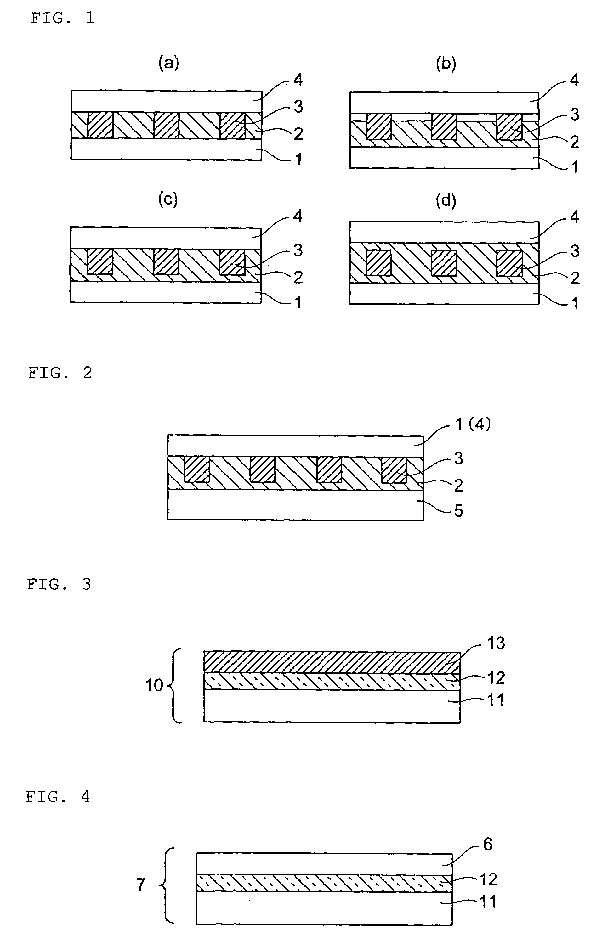
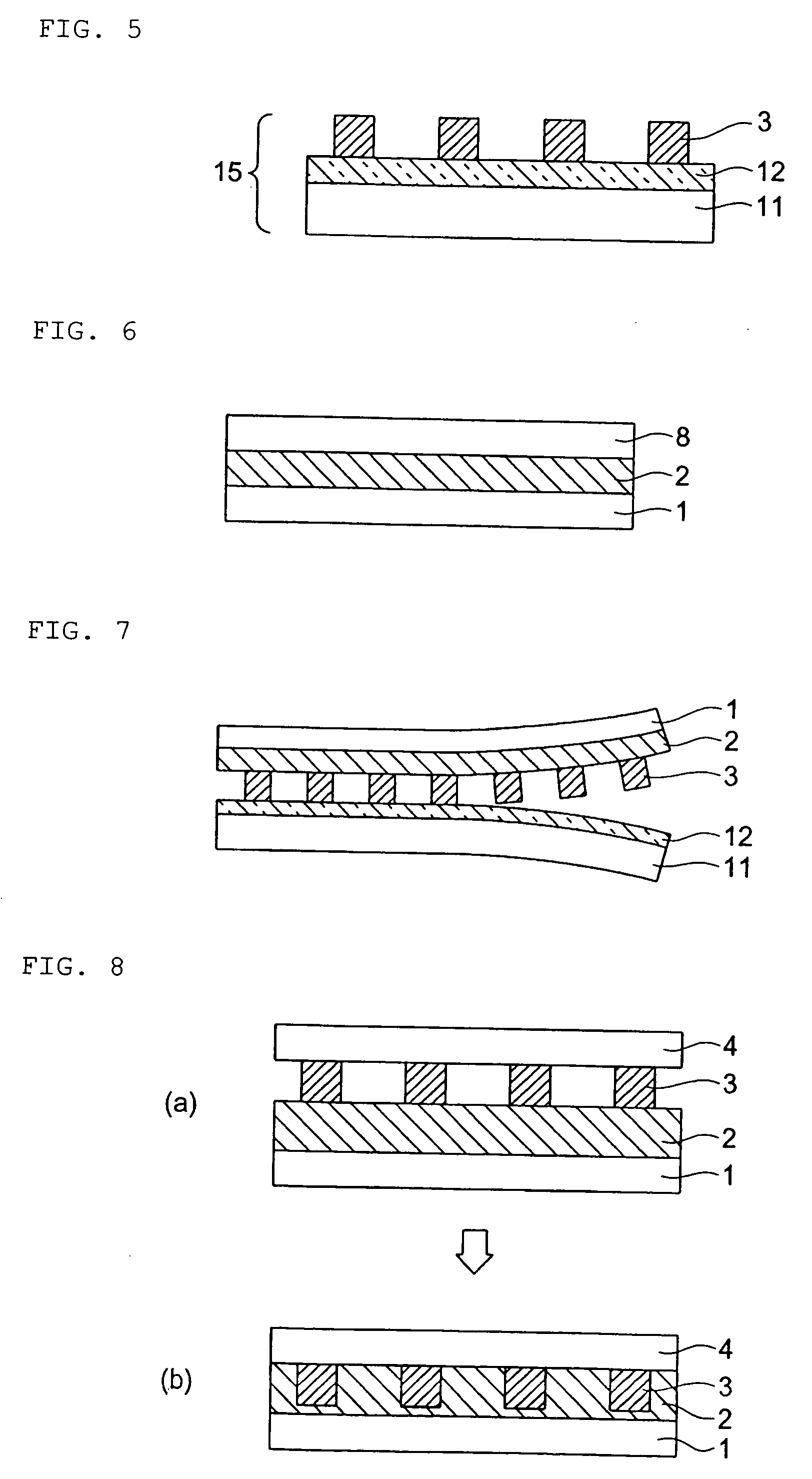
Disclosed is an electronic shielding light-transmitting member having an adhesive (2) and an electromagnetic shielding material (3) between two release films (1) and (4). By removing one of the release films (1) and (4) from the electronic shielding light-transmitting member and bonding the member to an optical filter or a plasma panel, there can be obtained an optical filter or a plasma panel having an electromagnetic shielding layer of excellent transparency.

Description

TECHNICAL FIELD[0001]The present invention relates to an electromagnetic shielding light-transmitting member, a method for manufacturing the member, an optical filter using the member, and a display panel such as a plasma display panel formed by using the member.BACKGROUND ART[0002]In various displays such as plasma display and EL display that have prevailed in recent years, and CRT, there has been a problem that an electromagnetic wave (a microwave) is generated from a display and the electromagnetic wave has a harmful influence on other devices. There is also a problem that the microwave may have a harmful influence on the human body. In particular, concerning the plasma display, it is a problem because a stronger electromagnetic wave compared with other displays is generated and leaks since the plasma display panel is driven a thigh-voltage. In order to shield the electromagnetic wave leaking from the front face of these various displays, the space may be insulated electromagneti...

Claims


Application Information

Patent Timeline
Patent Type & Authority Applications(United States)
IPC IPC(8): H01J61/35B32B15/095G02B5/22H01J9/00
CPCH05K9/0096Y10T428/1438Y10T428/1467G02B1/00
Inventor USUI, SHINICHIUEDA, YUKIHIROMACHIDA, TOSHINORINAKAMURA, NAOTOSHIKATO, SHIGEMOTOTOKUTOME, KAZUHITO
Owner TOPPAN PRINTING CO LTD
Learn More