
Image sensor device with submicron structure

Active Publication Date: 2009-09-03
VISERA TECH CO LTD
View PDF4 Cites 18 Cited by
  • Summary
  • Abstract
  • Description
  • Claims
  • Application Information

AI Technical Summary

Benefits of technology

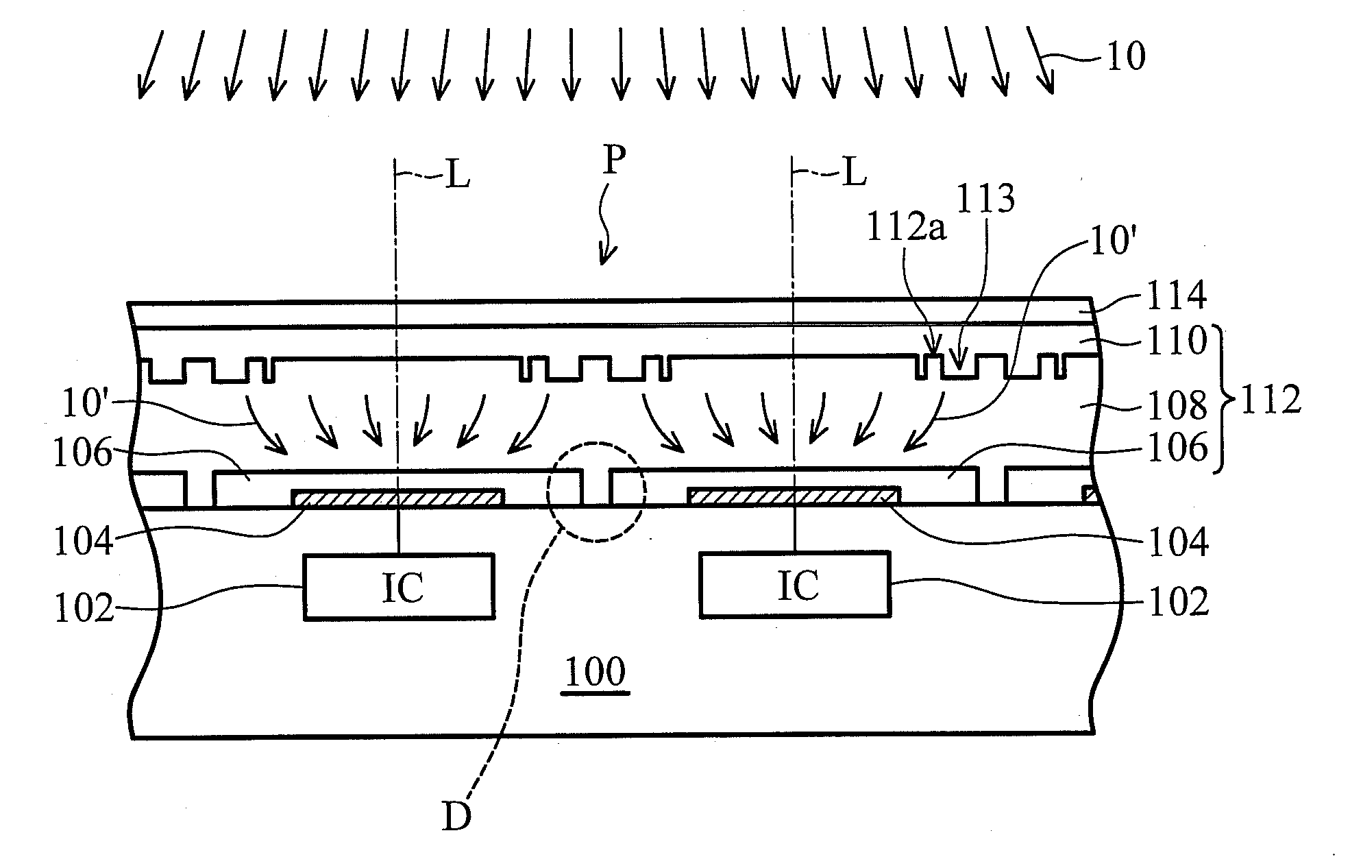
[0005]In order to improve image sensor device performance, laterally integrated CMOS image sensor devices, which use CMOS circuitry in each pixel and photodiodes for light sensing devices, have been developed. The CMOS circuitry increases sensitivity and reduces noise, allowing pixel size to shrink while maintaining functionality. For a typical laterally integrated CMOS image sensor device, the photodiode and the CMOS circuitry are formed next to each other on a silicon substrate. Thus, fill factor is reduced, lowering the sensitivity of sensors. If pixel size increases to maintain sensitivity, resolution will be reduced.

Problems solved by technology

However, as the pixel size is reduced in order to form more pixels to increase resolution, the fill factor is reduced and results in an increase in the dark current due to increased dead zones between pixels, thus aggravating image lag effect.
The dead zone of the photodiode is a region where the transfer efficiency of optical charges is poor and dark current is generated due to thermal generation of charge carriers, thus no signal is generated at the dead zone when light enters the photodiode.

Method used


Image

  • Image sensor device with submicron structure
  • Image sensor device with submicron structure
  • Image sensor device with submicron structure

Examples


Embodiment Construction

[0013]The following description is of the best-contemplated mode of carrying out the invention. This description is provided for the purpose of illustrating the general principles of the invention and should not be taken in a limiting sense. The scope of the invention is best determined by reference to the appended claims.

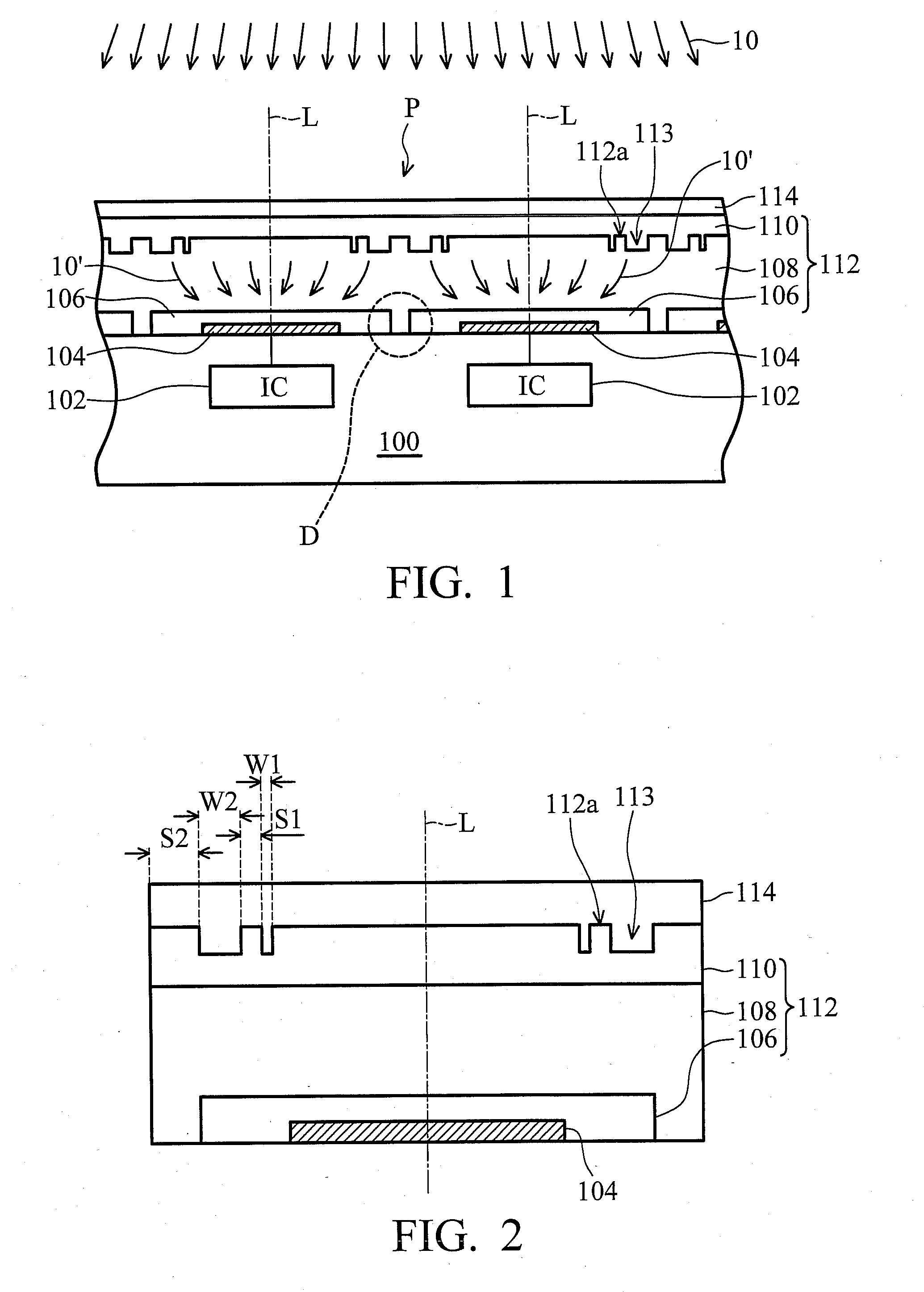
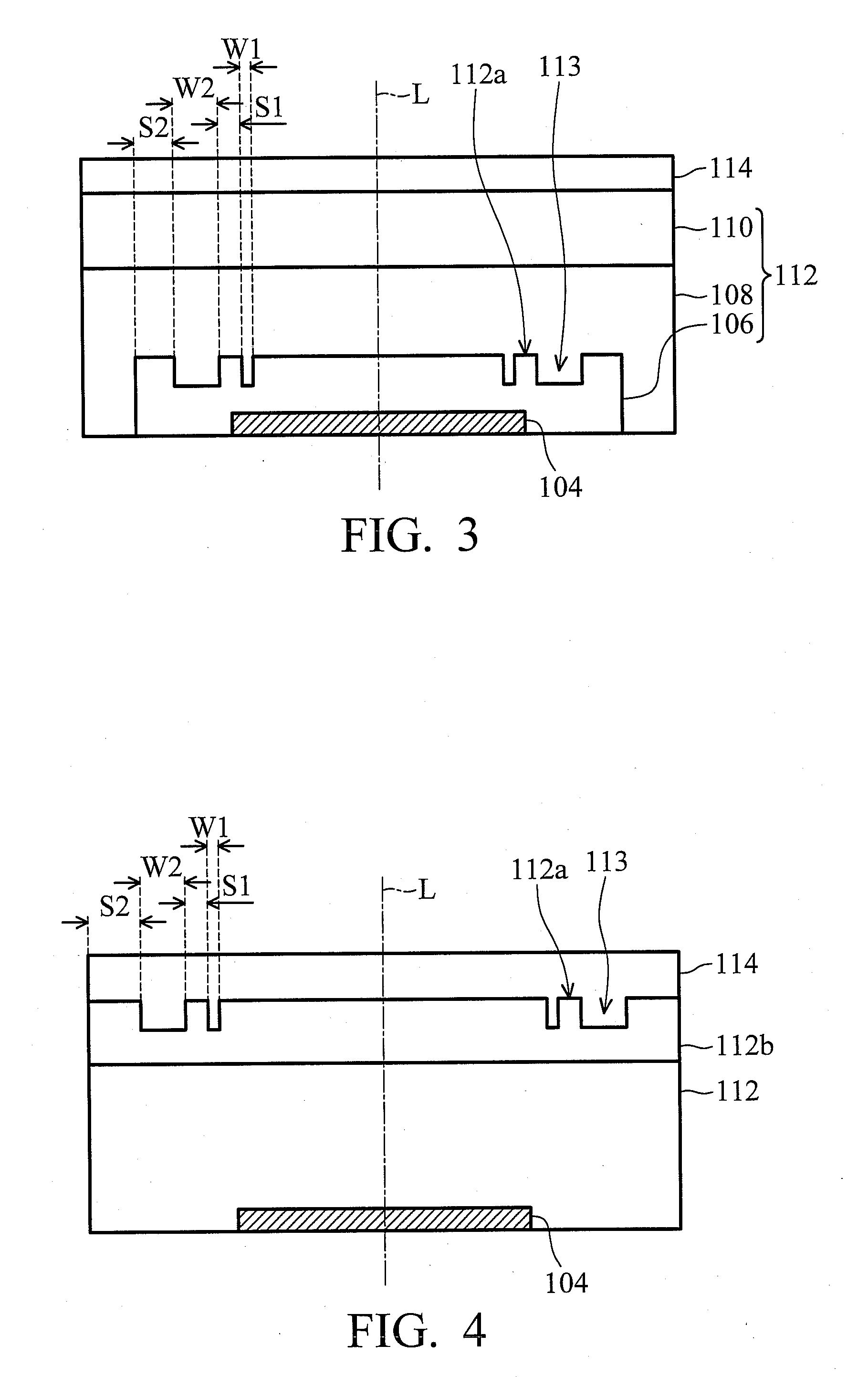
[0014]FIG. 1 illustrates an exemplary embodiment of an image sensor device according to the invention. The image sensor device comprises a substrate 100 and a plurality of photodiodes disposed thereon. The substrate 100 may comprise silicon or other well known semiconductor material in the art, having a pixel region P for arrangement of a pixel array (not shown) thereon. Each unit pixel in the pixel array includes a corresponding photodiode on the substrate 100 for converting a photo signal from an incident light 10 into an electronic signal. In the embodiment, a plurality of integrated circuits (ICs) 102 is disposed in the substrate 100 of the pixel region P and i...


PUM


Abstract

An image sensor device is disclosed. The image sensor device comprises a substrate having a pixel region and at least one integrated circuit in the substrate of the pixel region. A photodiode is disposed on the substrate of the pixel region, comprising a lower electrode, a transparent upper electrode and a photoelectric conversion layer. The lower electrode is disposed on the substrate and is electrically connected to the integrated circuit. The photoelectric conversion layer is disposed on the lower electrode and has a submicron structure therein. The transparent upper electrode is disposed on the photoelectric conversion layer.

Description

BACKGROUND OF THE INVENTION[0001]1. Field of the Invention[0002]The invention relates to an optoelectronic device and more particularly to an image sensor device using a subimcron structure.[0003]2. Description of the Related Art[0004]As optoelectronic devices become more and more popular, such as digital camera, digital video recorder, image capture cap able mobile phone and monitor, demand for image sensor devices accordingly increase. An image sensor device is used to record and change a photo signal from an image to an electronic signal. After recording and processing the electronic signal, a digital image is generated. In general, image sensor devices can be categorized into two main types, one is charge coupled devices (CCD) and the other complementary metal oxide semiconductor (CMOS) devices.[0005]In order to improve image sensor device performance, laterally integrated CMOS image sensor devices, which use CMOS circuitry in each pixel and photodiodes for light sensing devices...

Claims


Application Information

Patent Timeline
IPC IPC(8): H01L31/00
CPCH01G9/2031H01G9/2059Y02E10/542H01L27/14632H01L27/14692H01L27/14627Y02E10/548
Inventor LEE, HSIAO-WEN
Owner VISERA TECH CO LTD
Learn More