Optical gas detection

a gas detection and optical technology, applied in the field of infrared gas detection, can solve the problems of infrared radiation attenuation, radiation scattering at the surface, contamination of surfaces,

Active Publication Date: 2009-09-17
HONEYWELL ANALYTICS AG
View PDF9 Cites 19 Cited by
  • Summary
  • Abstract
  • Description
  • Claims
  • Application Information

AI Technical Summary

Benefits of technology

[0027]The radiation reflected by the said optics surface may be focused by a further lens onto the detector; this further lens may provide a useful support for mounting the second deflector.
[0028]A shield is preferably arranged to block radiation that is directed to

Problems solved by technology

However, factors other than absorption by the target gas also attenuate the infrared radiation, including obscuration of the detecting beam, atmospheric scattering of the radiation, contamination of the surfaces, e.g. by dirt or condensation, and ageing of components.
The provision of point gas detectors gives rise to problems when monitoring a large area since the placing of numerous detectors throughout the area is expensive.
Furthermore, if the build up of target gas takes place between detectors, it will not be detected.
At such low levels, the noise in the detector can be greater than the signal of the target gas, making it very difficult to detect such low levels of toxic target gases.
In addition, the signal can become indiscernible due to drift in electronic or optical components over time, variations in temperature and/or atmospheric conditions, etc.
In addition, the use of coherent laser irradiation from a tuneable laser diode can give rise to interference fringes where the variation in the intensity of the radiation between the bright and dark fringes far exceeds the signal arising from the presence of low levels of the target gas.
Accordingly, no low cost reliable open path gas detector for toxic gases measuring target gas levels as low as 10

Method used


Image

  • Optical gas detection
  • Optical gas detection
  • Optical gas detection

Examples


Embodiment Construction

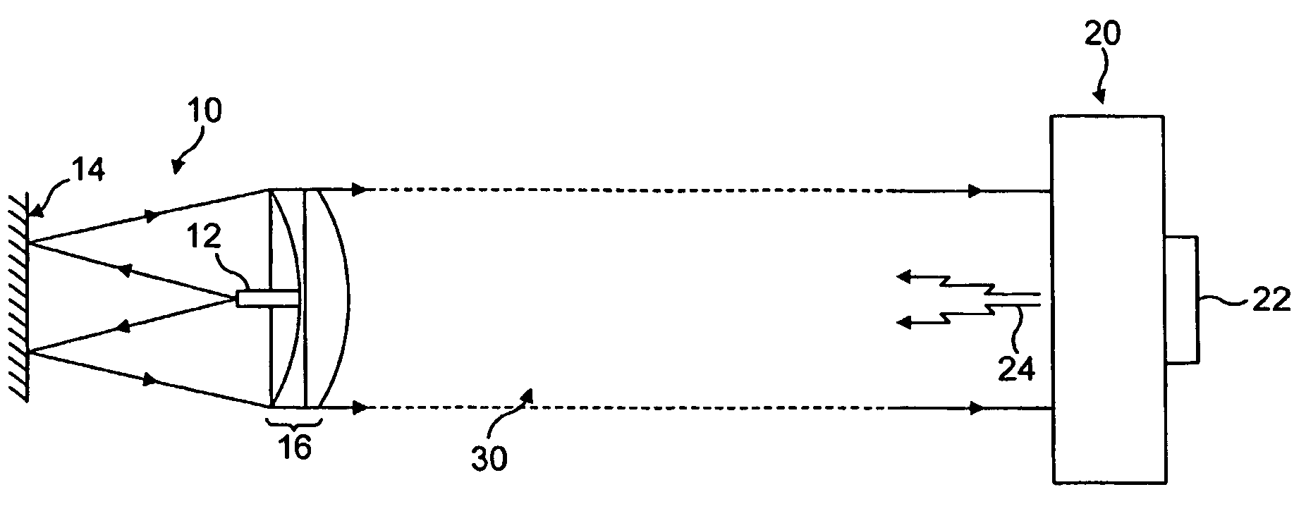
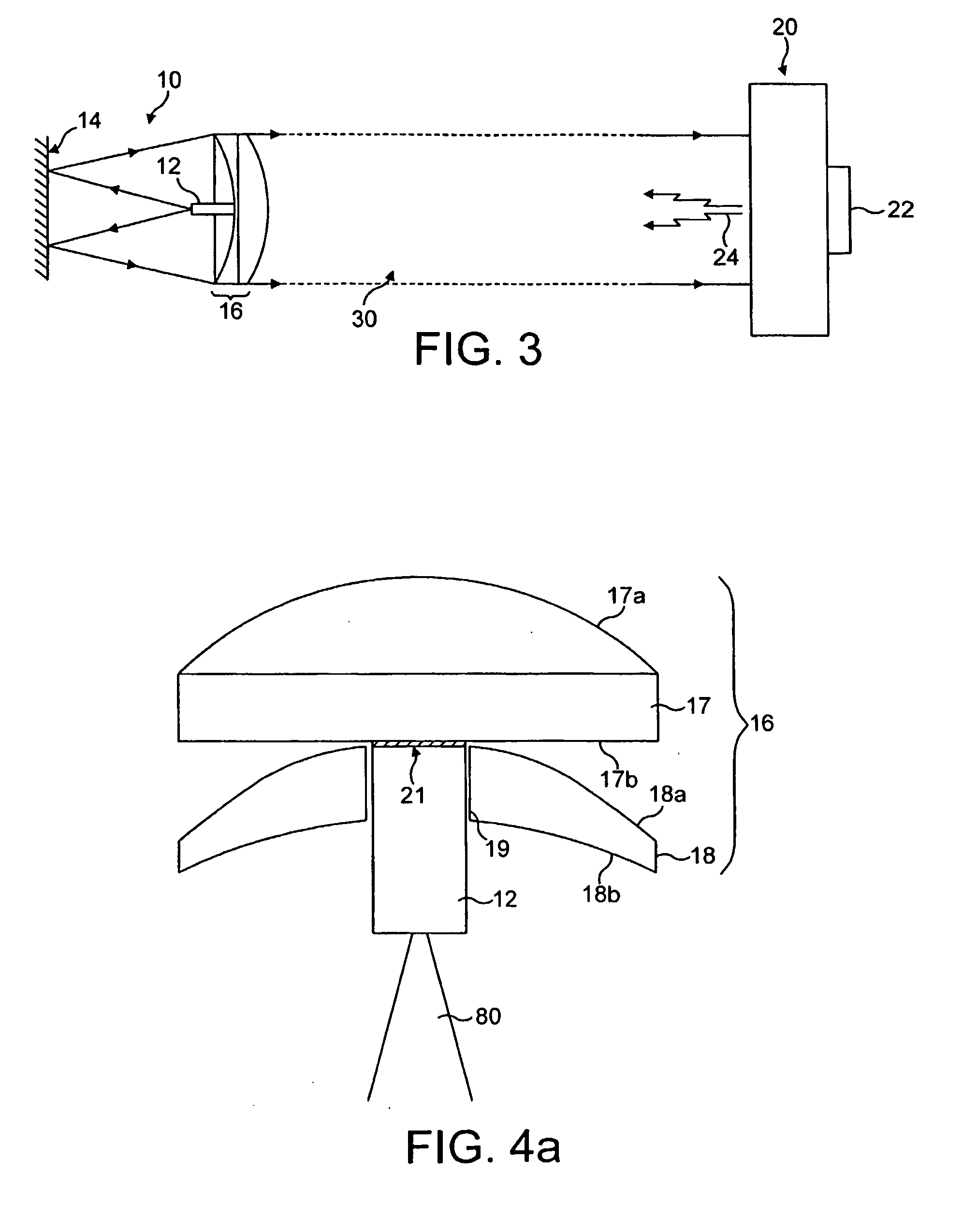
[0124]FIG. 3 is a schematic representation of an open path gas detector according to the present invention, which includes a transmitter unit 10 and a detector unit 20. The transmitter unit transmits a parallel beam of radiation, which is generally denoted by the reference number 30, along a measuring path that can be a substantial length, for example 20 to 1,000 m.

[0125]The transmitter unit 10 includes a tuneable laser diode 12 that produces a beam of infrared radiation in a very narrow wavelength band that is directed rearwardly at a steerable mirror 14, that reflects the radiation towards an arrangement of optics 16 that collimates the beam reflected by the mirror to form the parallel beam 30 directed along the measurement path at the detector unit 20. The detector unit 20 includes filters (not shown) for filtering out radiation in wavelengths that are not of interest. After passing through the filters, the radiation is incident on a detector 22 that produces a signal that gives ...


PUM


Abstract

The present invention provides a transmitter unit for an open path gas detector for detecting a target gas and comprises: a radiation transmitter, e.g. a tuneable laser diode, capable of emitting radiation at a wavelength absorbed by the target gas, and a radiation deflector, having a deflecting part and a non-deflecting part, e.g. a mirror having a non-reflective part. The deflecting part and the non-deflecting part are located in the path of the radiation emitted by the transmitter and the non-deflecting part does not deflect the said radiation emitted by the transmitter or does so to a different extent than the deflecting part. In this way, the beam has a core in shadow that can be used to align the beam with a receiver unit. The radiation deflector is preferably a mirror having a reflective surface for reflecting radiation emitted by the transmitter and a non-reflective part that does not reflect the said radiation emitted by the transmitter or does so to a lesser extent that the reflecting surface. The non-reflective part is preferably transparent so that it allows radiation to pass through it, which can be used to measure the wavelength of the transmitter and, if necessary correct it.

Description

INDUSTRIAL FIELD[0001]The present invention relates to the infrared detection of gases, which term also includes vapours. It especially concerns open path gas detectors that are used to detect gases and that include a transmitter unit that transmits a beam of radiation across a path in a space being monitored and a detecting unit that detects the radiation that has passed across the space. The term “open path gas detector” is used to cover detectors irrespective of the length of the path and irrespective of whether the path is open to atmospheric conditions and / or is enclosed.BACKGROUND ART[0002]The use of non-dispersive infrared spectroscopy to detect hydrocarbon gases is well established. It essentially involves transmitting infrared radiation along a path in an area being monitored; the wavelength of the infrared radiation is chosen so that it is absorbed by the gas of interest (hereafter called the “target gas”) but not substantially absorbed by other gases in the atmosphere of ...

Claims


Application Information

Patent Timeline
IPC IPC(8): G01N21/59G01N21/3504
CPCG01N21/3504G01N2021/3595G01N2021/1793G01N21/39G01N21/15G01N2021/158G01N2021/3513
Inventor SUTTON, STEPHEN N.WATTS, RODNEY ROYSTONPROCTOR, MICHAEL
Owner HONEYWELL ANALYTICS AG
Why Eureka
Try Eureka