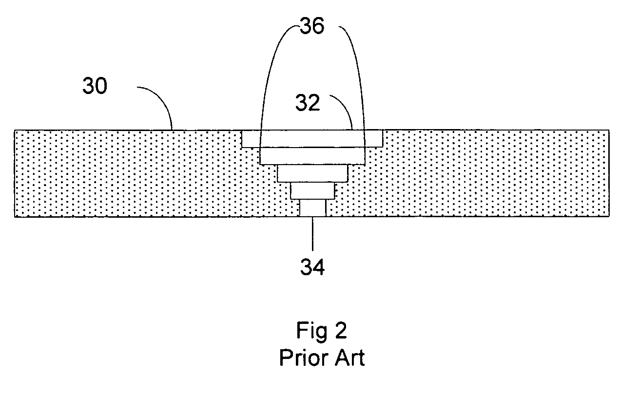
[0011]To achieve this effect, the holes have to be drilled very precisely. First the spacing of the holes has to be carefully controlled in order to achieve the correct light output from the finished workpiece. Second, the exit
diameter of the holes has to be exact in order to be virtually undetectable when unlit. Third, the taper of the holes has to be exact in order to gather the correct amount of light and to allow viewing from a consistently wide angle. Fourth, the finish of the inside of the hole needs to be controlled in order to promote even illumination over the desired viewing angle. Finally, the exit hole should be free of debris in order to enhance the virtual
invisibility of the unlit hole. In addition these holes are sometimes filled with light conducting material to prevent gas or liquids from penetrating the hole and for
mechanical stability. In this case the smooth sidewalls enhance the ability to fill the holes and increase the adhesion between the sidewalls and the filler.
[0012]In one embodiment hole quality is improved by moving the focal point of the beam from being coincident with the surface of the workpiece being machined. Rather than focus the beam to match the power and 1 / e2
diameter of the laser pulse to the desired exit diameter and set the focal point at the surface of the workpiece, the laser beam path is aligned to the center of the desired hole location and the focal point is set a precise distance above or below the top surface of the workpiece. Typical ranges for the distance above or below the workpiece range from 1 to 1000 microns, or more preferably 10 to 500 microns, or even more preferably 50 to 200 microns. The spot size is then adjusted to yield the desired exit hole diameter. Preferred 1 / e2 spot sizes as measured at the surface of the workpiece range from 1.5 times the desired exit hole to 10 times the exit hole diameter, more preferably 2 times the diameter to 5 times the diameter, and even more preferably from 1.5 times the diameter to 2.5 times the diameter. Power is then adjusted to yield the fastest drilling time consistent with achieving the desired exit diameter.
[0014]Another benefit of using this method to
drill holes is that once the 1 / e2 diameter is selected, the exit diameter of the hole is relatively insensitive to changes in
pulse energy. Relatively large changes in pulse power or duration result in small changes in the exit hole diameter. This is illustrated in FIG. 3b, which shows cross-sectional views of the spatial power distribution of a
Gaussian pulse 50 with peak power 51 and a second
Gaussian pulse 53 with peak power 52 that is 125% of the peak power 51 of the first
Gaussian pulse, while maintaining the same 1 / e2 diameter 56. Because of the slope of the Gaussian at the
ablation thresholds 54 and 55, the difference between the
ablation diameter 57 of the first pulse and the
ablation diameter of the second pulse 58 is far less than 25%, thus proving that changes in peak power of Gaussian pulses cause correspondingly less change in the ablation diameter of the pulse. Thus, the size of the exit diameter of the drilled hole is relatively insensitive to changes in peak power of the pulse.
[0015]A third benefit of this method is that drilling holes in this fashion left the interior surface of the hole with a smooth, tapered finish, which improves the ability of the hole to transmit light evenly. The taper produced with this method is very consistent and relatively insensitive to peak power and number of pulses.
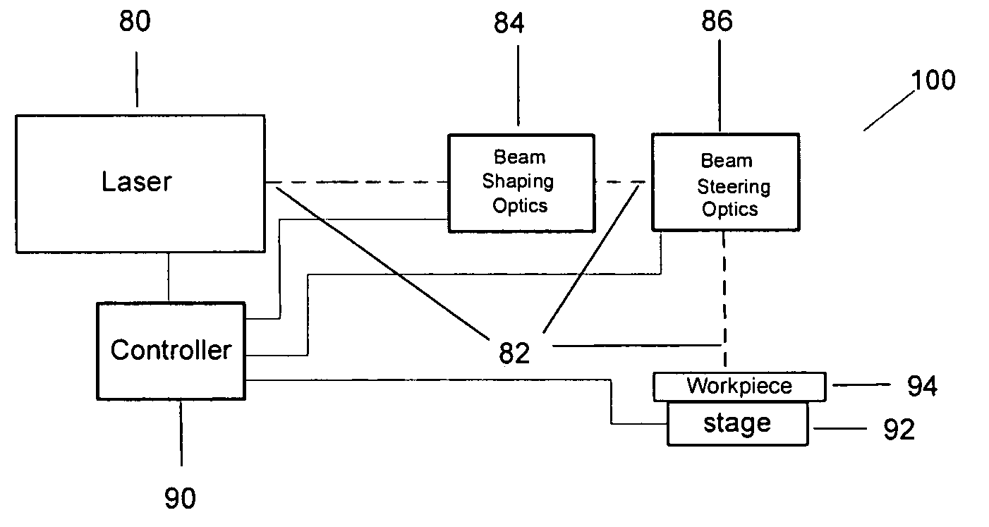
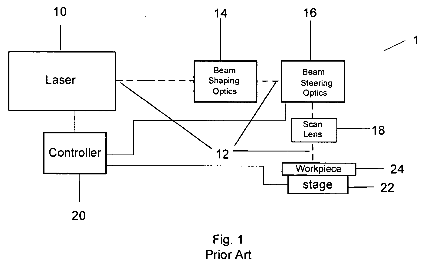
[0017]The result of this approach is that it dispenses with the need for an f-theta or scan lens placed after the
beam steering component. An f-theta, or scan lens, is typically required for precision micromachining systems that employ
beam steering optics for two reasons. The first is that transmitting a tightly focused laser pulse through
beam steering optics increases the
path length in a variable fashion, thereby making it difficult to maintain the focal spot at the precise location with respect to the workpiece. In addition, the f-theta lens allows the laser beam path to be perpendicular to the workpiece over the entire range of travel of the beam steering
optics, which is required when
trepanning is used to
drill the holes. Using a larger
focal spot size increases the
depth of field enough to eliminate the need for an f-theta lens. More particularly, the weak focusing required by this method combined with the use of Gaussian spot geometry means that the lens can be a standard lens instead of and f-theta lens. In addition, the lens can be place either in front of or behind the steering mirrors with no change in performance of the
system. In addition, the superior hole geometry and smooth finish eliminate the need for precise perpendicularity over a scan area large enough to be useful for the applications described herein.

