Honeycomb structure

Active Publication Date: 2009-10-01
NGK INSULATORS LTD
View PDF14 Cites 34 Cited by
  • Summary
  • Abstract
  • Description
  • Claims
  • Application Information

AI Technical Summary

Benefits of technology

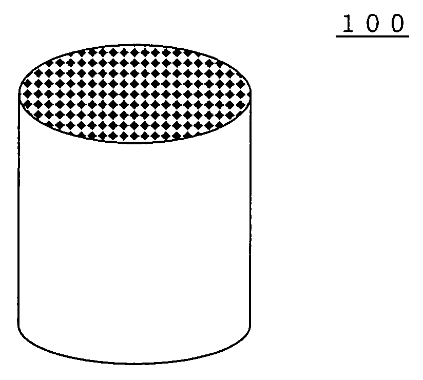
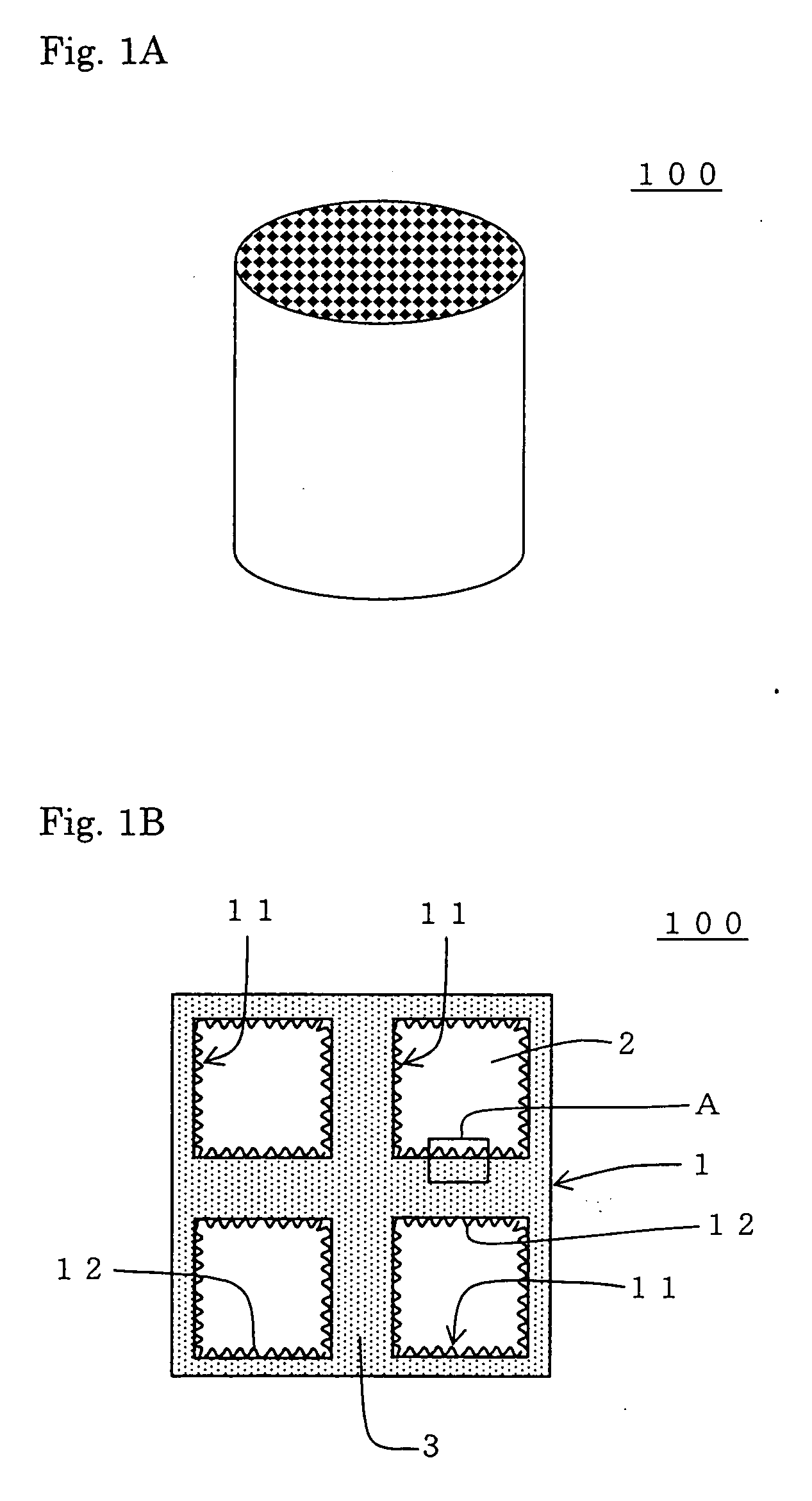
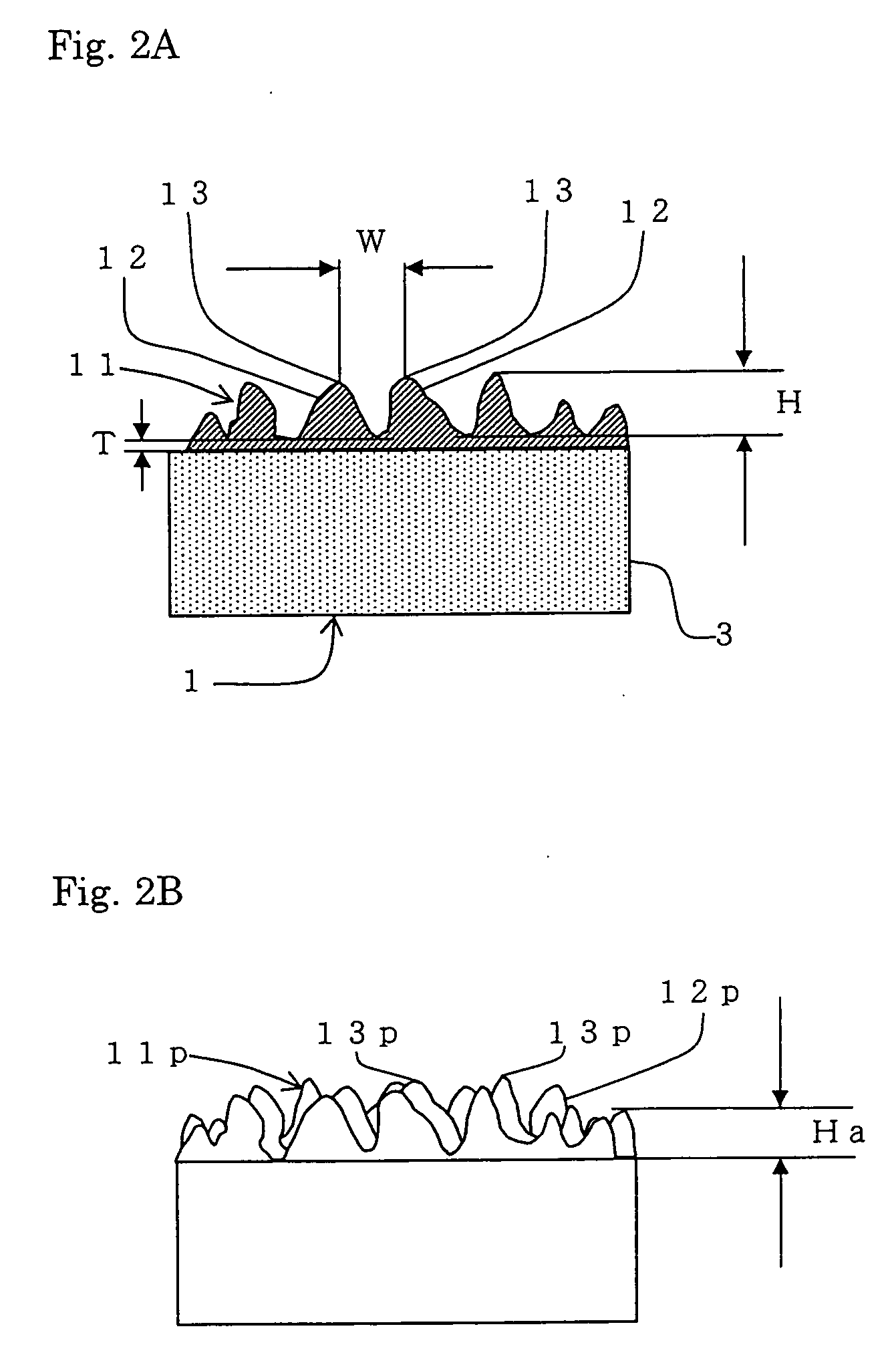
[0019]A honeycomb structure of the present invention is provided with a porous coat layer for inhibiting microparticles from entering on the surface of the partition walls, and the surface of the coat layer has an uneven shape for increasing the surface area of the surface of the coat layer. Therefore, when combusting and removing the trapped particulate matter contained in exhaust gas with loading a catalyst on a surface of the coat layer, the particulate matter can be trapped o

Problems solved by technology

When the pore diameter of the partition walls is increased, a large amount of particulate matter enters the pores to cause clogging of the pores, thereby causing a problem of increase in pressure loss upon treating exhaust gas.
However, passages in the walls are narrow to cause a problem of increasing pressure loss before the particulate matter deposits.
However, particularly in the presence of a loaded catalyst, since particulate matter does not enter the pores, particulate matter is hardly br

Method used


Image

  • Honeycomb structure
  • Honeycomb structure
  • Honeycomb structure

Examples


example 1

[0094]To 100 parts by mass of a cordierite-forming raw material prepared by combining a plurality selected from talc, kaolin, calcined kaolin, alumina, calcium hydroxide, and silica at a predetermined ratio to obtain a chemical composition of 42 to 56% by mass of SiO2 (silica), 0 to 45% by mass of Al2O3 (alumina), and 12 to 16% by mass of MgO (magnesia) were added 12 to 25 parts by mass of graphite as a pore former and 5 to 15 parts by mass of synthetic resin. After suitable amounts of methyl celluloses and a surfactant are added to them, water was added, followed by mixing them to prepare kneaded clay. After vacuum deairing the kneaded clay, the kneaded clay was extrusion-formed to obtain a honeycomb formed article. Next, the honeycomb formed article was fired to obtain a honeycomb fired article (porous substrate). The firing conditions were 1400 to 1430° C. and 10 hours.

[0095]Next, plugging was performed to the honeycomb fired article. A mask was alternately applied on cell openin...

example 2

[0113]A porous substrate was manufactured in the same manner as in Example 1. A honeycomb structure having a catalyst loaded thereon was manufactured in the same manner as in Example 1 except that the particle size and the amount of the protrusion-forming material were adjusted. The coat layer obtained had a thickness of 15 μm, a porosity of 70%, and an average pore diameter of 15 μm. In the same manner as in Example 1, the average height of the protrusions (average protrusion height) average interval between the protrusions (average protrusion interval), surface area ratio, cell hydraulic diameter, pressure loss ratio, and regeneration time ratio were measured. The results are shown in Table 1.

example 3

[0114]The porous substrate was manufactured in the same manner as in Example 1. A honeycomb structure having a catalyst loaded thereon was manufactured in the same manner as in Example 1 except that the particle size and the amount of the protrusion-forming material were adjusted. The coat layer obtained had a thickness of 15 μm, a porosity of 70%, and an average pore diameter of 15 μm. In the same manner as in Example 1, the average height of the protrusions (average protrusion height) average interval between the protrusions (average protrusion interval), surface area ratio, cell hydraulic diameter, pressure loss ratio, and regeneration time ratio were measured. The results are shown in Table 1.


PUM

PropertyMeasurementUnit
Pore sizeaaaaaaaaaa
Pore sizeaaaaaaaaaa
Heightaaaaaaaaaa

Abstract

A honeycomb structure includes: a porous substrate having porous partition walls separating and forming a plurality of cells functioning as fluid passages, a porous coat layer disposed on a surface of the partition walls to inhibit microparticles from entering, a surface of the coat layer having an uneven shape to increase a surface area, and plugging portions for plugging cells so that a fluid flowing into the structure from an opening portions on one end side of predetermined cells may pass through the partition walls and flows out from opening portions on the other side of the other cells to allow the gas to flow through the partition walls and the coat layers. The honeycomb structure can inhibit the pressure loss from increasing upon trapping particulate matter in exhaust gas and can effectively combust and remove the trapped particulate matter.

Description

BACKGROUND OF THE INVENTION AND RELATED ART STATEMENT[0001]The present invention relates to a honeycomb structure. More specifically, the present invention relates to a honeycomb structure capable of inhibiting pressure loss from increasing upon trapping particulate matter in exhaust gas and effectively combusting and removing the trapped particulate matter.[0002]There is a growing requirement for removing particulate matter in exhaust gas discharged from internal combustion engines such as an automobile engine, a construction machine engine, and an industrial machine stationary engine, other burning appliances, and the like in consideration of an influence on environment. Therefore, a honeycomb structure made of ceramic or the like is widely used as a filter (diesel particulate filter: DPF) for removing particulate matter. As a DPF, there is used a filter having a structure where predetermined cells having openings on one end and plugged end portions on the other side and the other...

Claims


Application Information

Patent Timeline
IPC IPC(8): B32B3/12
CPCB01D46/2429B01D46/2451B01D46/2455B01D46/2466B01D46/247B01D2046/2437Y10T428/24149B01D2046/2485B01D2046/2496B01D2279/30F01N3/0222Y02T10/20B01D2046/2481Y02T10/12B01D46/2498B01D46/24492B01D46/2484B01D46/2482B01D46/2474
Inventor YAMAGUCHI, SHINJI
Owner NGK INSULATORS LTD
Why Eureka
Try Eureka