Vacuum processing apparatus

Inactive Publication Date: 2009-10-08
HITACHI HIGH-TECH CORP
View PDF4 Cites 7 Cited by
  • Summary
  • Abstract
  • Description
  • Claims
  • Application Information

AI Technical Summary

Benefits of technology

[0020]The present invention intends to provide a vacuum processing apparatus capable of also improving the throughput while decreasing the number of f

Problems solved by technology

As a result, failure such as disconnection occurs to lower the yield.
A problem is however, caused that the number of processable sheets of the samples per unit time is not actually increased as expected even when the number of processing chambers is increased.
One of the reasons is that improvement in the throughput of the lock chamber is difficult.
Accordingly, the speed for evacuation or vent cannot easily be increased, and this hinders improvement in the throughput of the lock chamber.
On the other hand, when it is intended to shorten the exhaust time in the existent 2-stage exhaust structure, it results in a drawback that the depressurization speed on the exhaust curve (b1), for example, just after starting the evacuation (portion for region ZA) exceeds a depressuriz

Method used


Image

  • Vacuum processing apparatus
  • Vacuum processing apparatus
  • Vacuum processing apparatus

Examples


Example

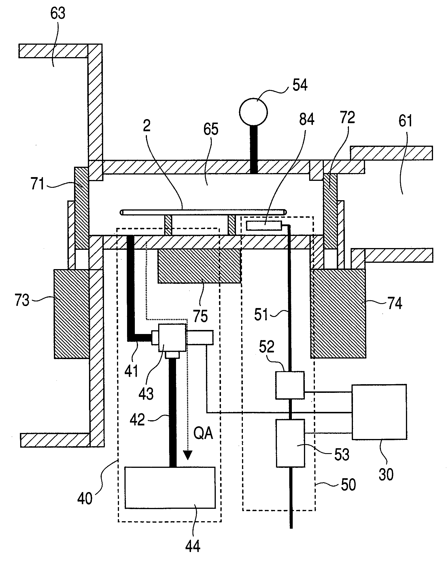
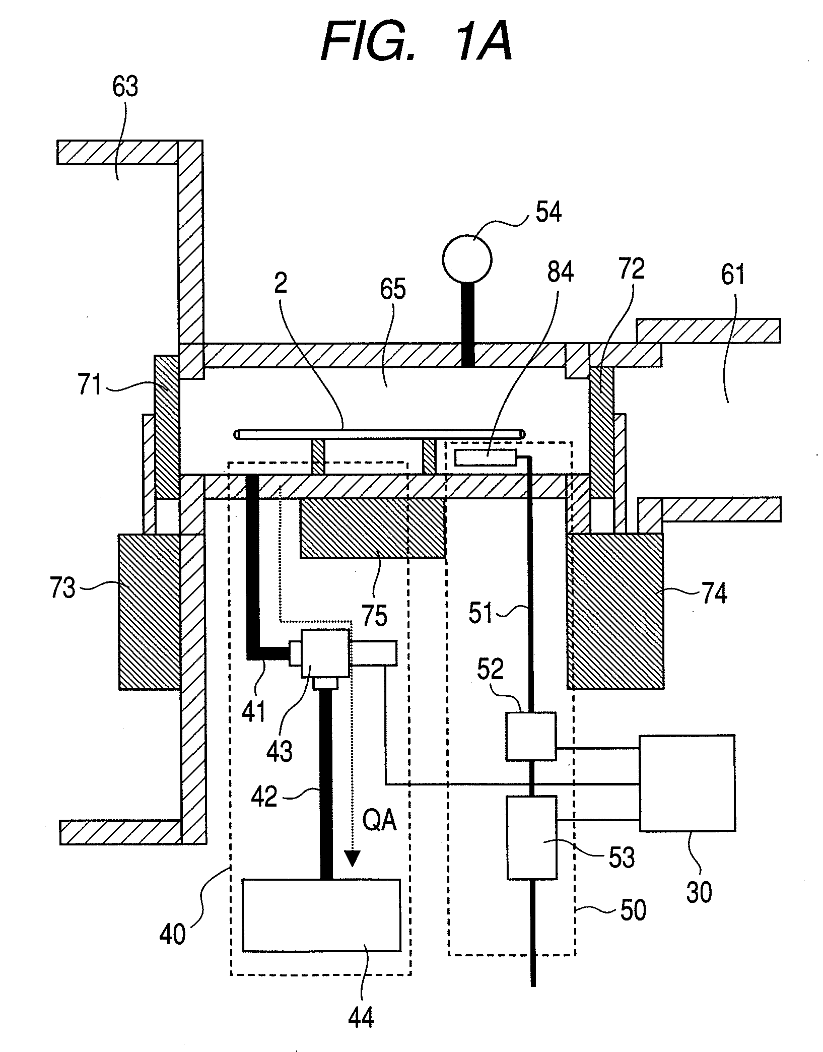
[0051]At first, a vacuum processing apparatus according to a first embodiment of the invention is to be described with reference to FIG. 1A to FIG. 11.

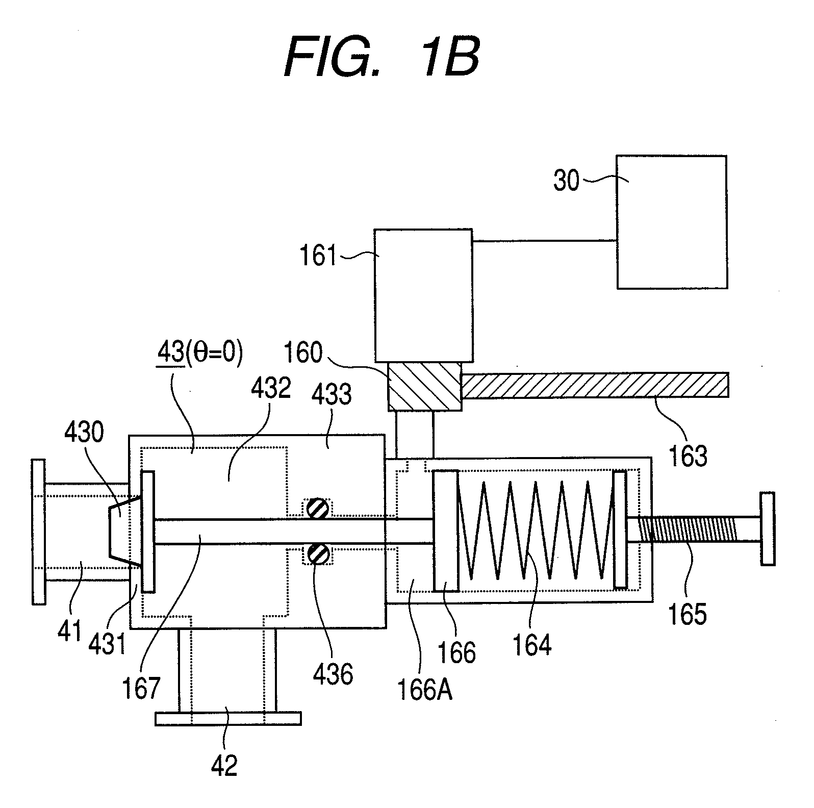
[0052]FIG. 1A shows an outline of a lock chamber disposed in a vacuum processing apparatus of the first embodiment. FIG. 1B shows a constitutional example of an open speed variable type valve disposed in a vacuum exhaust system of the first embodiment. FIG. 2A shows an example of the entire structure of a plasma etching apparatus applied with the first embodiment of the invention. FIG. 2B shows a cross sectional view along line B-B of the plasma etching apparatus shown in FIG. 2A as viewed from the lateral side. In FIG. 2B, the plasma processing chamber is not illustrated. Further, FIG. 2C is a view showing functional blocks of a controlling computer in FIG. 2A.

[0053]As shown in FIG. 2A, in the plasma processing apparatus of this embodiment, four vacuum processing chambers, that is, plasma processing chambers 60 (60-1 to 60-4) are con...

Example

Embodiment 2

[0097]Embodiment 1 discloses a valve of a type using pressurized air and controlling the moving speed of the valve body by the speed controller as an example of the open speed variable type valve 43, but the valve on-off control method may be those other than using the pressurized air so long as the moving speed of the valve body can be controlled.

[0098]Then, FIG. 12 shows another example of the open speed variable type valve. An open speed variable type valve 43 shown in FIG. 12 is adapted such that a valve body 430 can be controlled directly by a motor 161. When a gear 168-1 connected with a motor is rotated, a shaft 167 connected to a rack gear 168-2 moves rightward and leftward in FIG. 12 thereby opening or closing a valve body 430. The motor 161 is connected to a controlling computer 30 and adapted to control the on-off speed of the valve. Also in this example, the opening degree of the open speed variable type valve 43 is desirably controlled by the controlling com...

Example

Embodiment 3

[0100]Then, description is to be made for the method of controlling the depressurization speed of the lock chamber by the open speed variable type valve in the invention, that is, a method of acquiring various data stored in the memory as the data for executing the program for controlling the open speed variable type valve.

[0101]The depressurization speed of the lock chamber depends not only on the moving speed of the valve body (OPEN speed) but also on the volume on the side of the vacuum chamber, the volume of the pipeline in the exhaust line, and the exhaust performance of the pump. Accordingly, the depressurization speed is controlled by controlling the moving speed of the valve body after assembling the apparatus.

[0102]In this invention, this can be controlled by the controlling computer 30. An example of controlling the valve OPEN speed is to be described with reference to FIG. 13 and FIG. 14.

[0103]FIG. 13 shows the control sequence of the valve OPEN speed of the o...


PUM

PropertyMeasurementUnit
Pressureaaaaaaaaaa
Power densityaaaaaaaaaa

Abstract

A vacuum processing apparatus capable of attaining compatibility between the decrease for the number of foreign particles deposited on a sample in a lock chamber and improvement of the throughput, in which an open speed controllable valve is disposed and the depressurization speed can be controlled automatically by a controlling computer.

Description

CLAIM OF PRIORITY[0001]The present invention claims priority from Japanese Patent Application JP 2008-098193 filed on Apr. 4, 2008, the content of which is hereby incorporated by reference onto the application.FIELD OF THE INVENTION[0002]The present invention relates to a vacuum processing apparatus and more in particular to a vacuum processing apparatus having a lock chamber switched between an atmospheric pressure and a vacuum pressure for transferring samples, and vacuum processing apparatus, suitable for use in semiconductor manufacturing apparatus or semiconductor inspection apparatus.BACKGROUND OF THE INVENTION[0003]In manufacturing steps for semiconductor devices such as DRAM or micro processors, plasma etching or plasma CVD has been used generally. One of subjects in the manufacture of semiconductor devices includes decrease in the number of foreign particles deposited on a sample to be processed. For examples, when foreign particles drop on the fine pattern of a sample duri...

Claims


Application Information

Patent Timeline
IPC IPC(8): C23C14/00F04B49/00
CPCH01L21/67201Y10T137/85986
Inventor KOBAYASHI, HIROYUKIONO, KAZUYUKIMAEDA, KENJIIZAWA, MASARUYOKOGAWA, KENETSU
Owner HITACHI HIGH-TECH CORP
Why Eureka
Try Eureka