Solar-To-Electricity Conversion System Using Cascaded Architecture of Photovoltaic and Thermoelectric Devices

a conversion system and thermoelectric technology, applied in the field of solar electricity, can solve the problems of reducing conversion efficiency, affecting the efficiency of solar energy conversion, so as to achieve higher conversion efficiency, lower cost per output power, and high power output

Inactive Publication Date: 2009-10-08
PAN ERIC TING SHAN
View PDF68 Cites 12 Cited by
  • Summary
  • Abstract
  • Description
  • Claims
  • Application Information

AI Technical Summary

Benefits of technology

[0019]A key parameter is the conversion efficiency-the ratio of electrical power output over solar power impinging on the solar cell or module. Higher conversion efficiency means higher power output per unit collection area and lower cost per output power. Another key parameter is the concentration factor-the ratio of the concentrated solar radiation intensity at the focal area to the flux at its collector aperture or, equivalently, the ratio of the concentrated area at the focal point to the collector aperture area provided negligible loss of solar flux along the path of concentration optics. Higher concentration factor means smaller footprint of the conversion device and thus lower cost per output power.

Problems solved by technology

The concentration factor of these optical system collectors is primarily limited by the temperature-dependent efficiency and thermal stability of solar conversion method whether it is a working fluid in solar thermal or a conversion device in solar photovoltaic.
For multi-junction concentrator solar cells, it is found that conversion efficiency peaks out at about 600× before the thermal expansion mismatch and associated thermal effects of multiple stacking junctions or monolithically grown epitaxial layers become problematic.
In particular, residual stresses induced by thermal expansion mismatch induce defects and degrade conversion efficiency and occur in both lattice-matched and metamorphic (lattice-mismatched) epitaxial layered multi-junction solar cell structures.
The most significant obstacle to wide deployment of solar electricity has been the figure of merit in cost per watt or kilo-watt-hour generated by a given solar-to-electricity conversion method.
Current methods for manufacturing the solar power generation require significant capital investment to realize volume production.
Final products remain high in cost which has prevented penetration into the large utility and consumer markets as well as other niche markets.

Method used


Image

  • Solar-To-Electricity Conversion System Using Cascaded Architecture of Photovoltaic and Thermoelectric Devices
  • Solar-To-Electricity Conversion System Using Cascaded Architecture of Photovoltaic and Thermoelectric Devices
  • Solar-To-Electricity Conversion System Using Cascaded Architecture of Photovoltaic and Thermoelectric Devices

Examples


Embodiment Construction

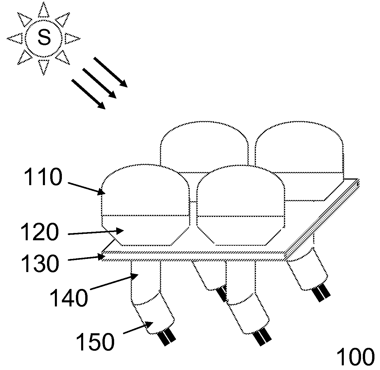
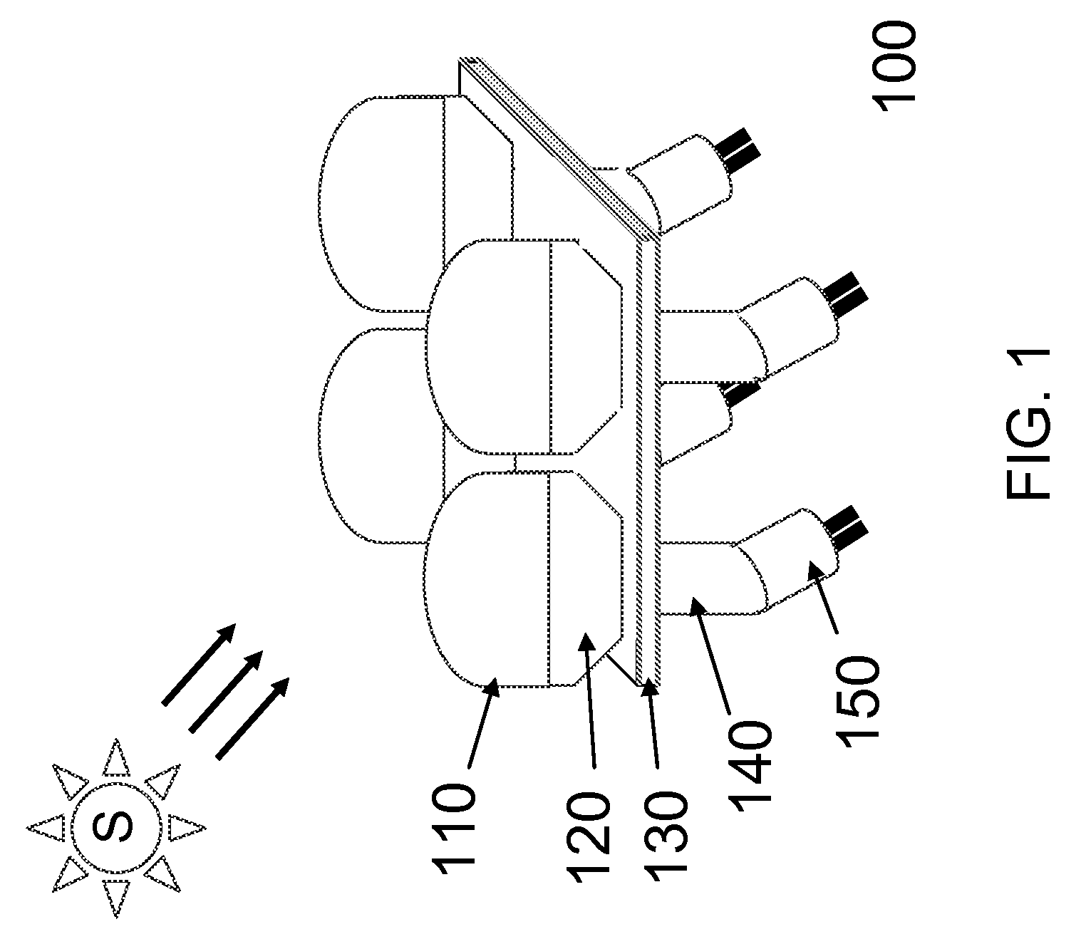
[0067]A novel modular platform integrates solid-state photovoltaic and thermionic or thermoelectric devices with the solar collection and concentration optics for the solar-to-electricity conversion. Both the conversion efficiency and the heat handling capability under a focal area of high solar concentration are increased by cascading photon-to-electricity devices such as photovoltaic devices and heat-to-electricity devices such as solid-state thermionic and thermoelectric devices, each of which is made of specific composition.

[0068]Embodiments of the present invention thus provide a conversion system that is scalable for the photovoltaic device of area from a few hundreds of micron square to a few tens of centimeter square with the corresponding optical collection area that gives a concentration factor from 250× to 5,000×. The overall conversion efficiency of the solid-state solar engine module of the present invention has potential to achieve 50% or more of which the conversion f...


PUM


Abstract

The invention addresses the area utilization and capital efficiency of systems for converting solar energy into electricity. A solid-state solar system includes photovoltaic and thermoelectric or thermionic cells. The system can be implemented in various configurations and by a solar insolation flux collection and concentration method to improve the area utilization and solar-to-electricity conversion efficiency. A thermal expansion matched multilayer board is also used to withstand ultra high concentration of solar insolation flux.

Description

RELATED APPLICATION DATA[0001]The present application claims the benefit under 35 U.S.C. 119(e) of the priority date of Provisional Application Ser. No. 61 / 043014 filed Apr. 7, 2008 which is hereby incorporated by reference. The application is further related to the following applications, all of which are filed on this same date and incorporated by reference herein:[0002]Solar-To-Electricity Conversion Sub-Module; Ser. No. ______ (attorney docket number 2009-1)[0003]Solar-To-Electricity Conversion System; Ser. No. ______ (attorney docket number 2009-2)[0004]Method for Solar-To-Electricity Conversion; Ser. No. ______ (attorney docket number 2009-3)FIELD OF THE INVENTION[0005]The present invention relates to the field of solar electricity and, more particularly, to the collection and conversion of solar energy into electricity using a concentrated optical system and other components such as light tubes, light guides, light fibers, or a light pipe for solar energy collection and solid...

Claims


Application Information

Patent Timeline
Patent Type & Authority Applications(United States)
IPC IPC(8): H01L31/042
CPCH01L31/052H01L35/30H05K1/0203H05K1/0274H05K1/0298H05K2201/09072H01L31/0547Y02B10/14Y02B10/20Y02B10/70Y02E10/52H02S10/10H01L31/0543H05K2201/10121H02S40/44Y02E10/60Y02B10/10H10N10/13
Inventor PAN, ERIC TING-SHAN
Owner PAN ERIC TING SHAN
Why Eureka
Try Eureka