

Electrophotographic photoreceptor, and image forming apparatus and process cartridge using the same
- Summary
- Abstract
- Description
- Claims
- Application Information
AI Technical Summary
Benefits of technology
Problems solved by technology
Method used
Image

Examples
example 1
Preparation of Electrophotographic Photoreceptor
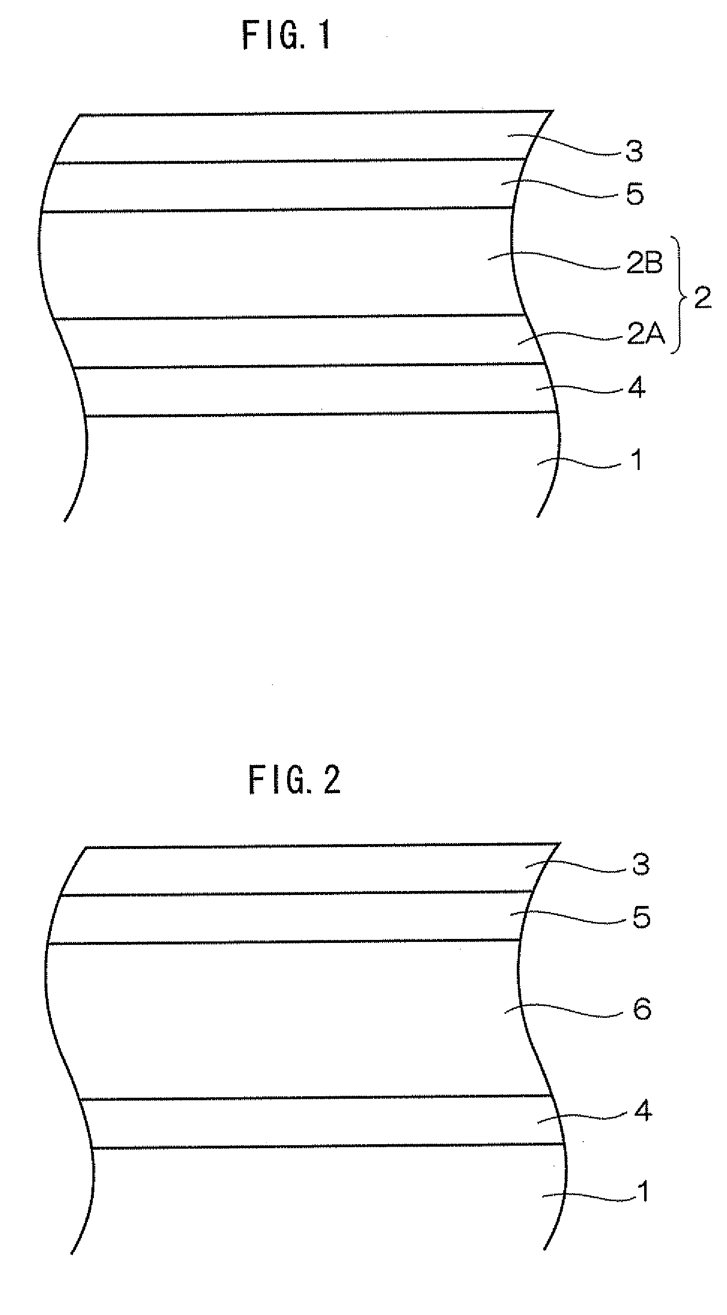
[0263]According to the following procedure, an undercoat layer, a charge generation layer, and a charge transport layer are formed on a substrate Al in this order to give an organic photoreceptor.
[0264]Formation of Undercoat Layer
[0265]One hundred parts by weight of zinc oxide (average particle diameter: 70 nm) are mixed with 500 parts by weight of tetrahydrofuran under stirring. To the mixture, 1.25 parts by weight of a silane coupling agent (trade name: KBM603, manufactured by Shin-Etsu Chemical Co., Ltd.) are added and stirred for 2 hours. Subsequently, baking is conducted to obtain a zinc oxide pigment whose surface is treated with the silane-coupling agent.
[0266]60 parts by weight of the surface-treated zinc oxide, 0.6 part by weight of alizarin, 13.5 parts by weight of a curing agent (blocked isocyanate, trade name: SUMIDUR 3175, manufactured by Sumika Bayer Urethane Co., Ltd.), and 15 parts by weight of a butyral resin (trade na...
example 9 and example 10
Formation of Surface Layer
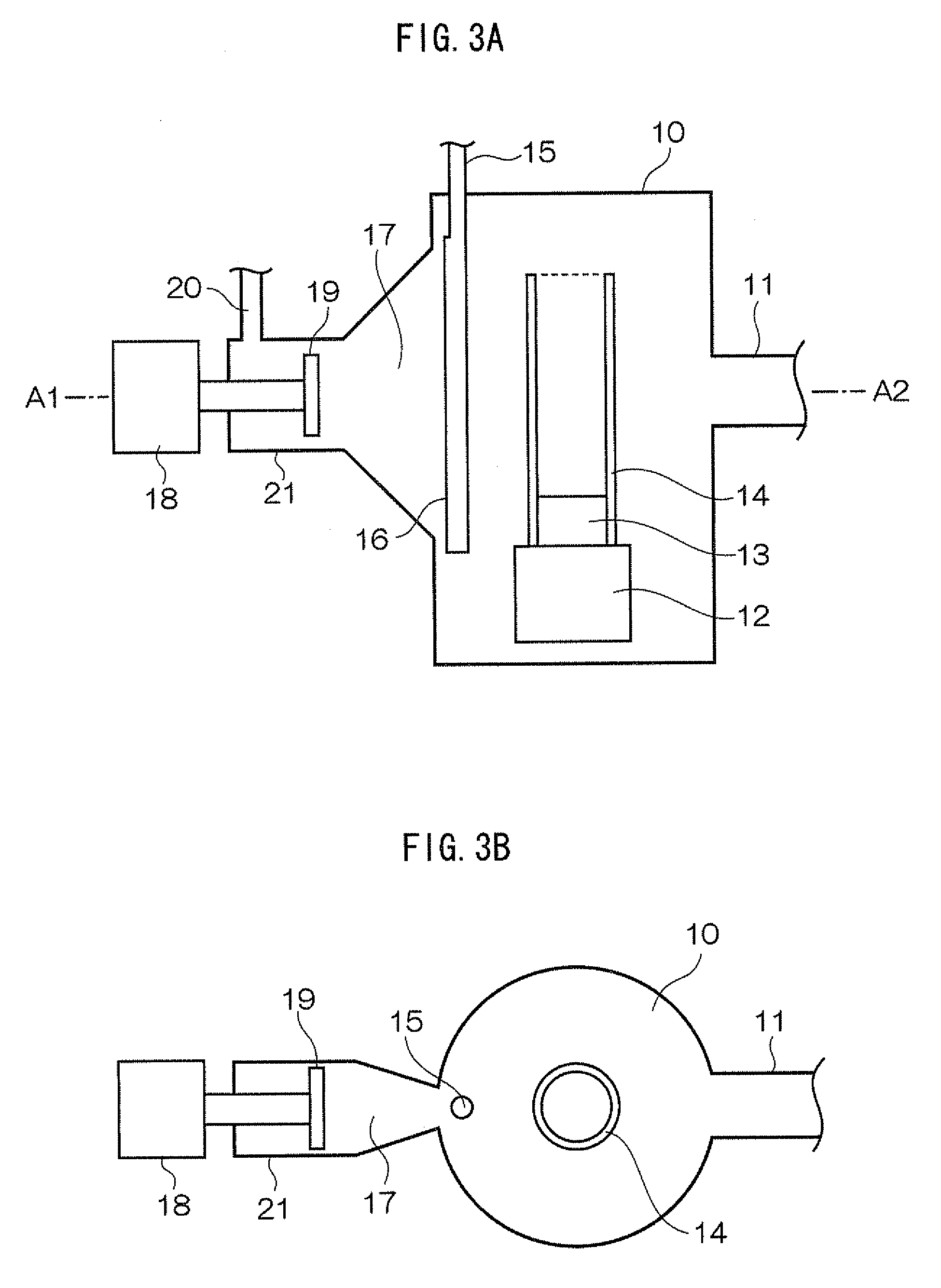
[0280]Subsequent to the formation of the intermediate layer, He gas, hydrogen gas, and oxygen gas diluted to 4% by He gas are mixed in a mixing device (not shown in drawings), and the mixture gas is introduced from a gas supply tube 20 towards an flat plate electrode 19 having a length of 350 mm at a flow rate of about 352 sccm (He gas: 150 sccm, hydrogen: 200 sccm, oxygen: 2 sccm). Electric discharge is performed from the flat plate electrode 19 by setting an output of 13.65 MHz radio frequency wave to 80 W with matching by a tuner, using a high-frequency power supply unit 18 and a matching circuit (not shown in the drawings). The reflected wave at discharge is 0 W.
[0281]Subsequently, trimethyl gallium gas is introduced from a shower nozzle 16 into a film-forming chamber 10 through a gas inlet tube 15 at a trimethyl gallium gas flow rate of 1.0 sccm. At this time, the reaction pressure in the film-forming chamber 10 determined by a Baratron vacuum gauge is...
examples 2 to 10
[0313]In Example 2 to 6, photoreceptors A2 to A6 in which an intermediate layer and an surface layer are formed on the non-coated photoreceptor in this order are prepared in the same manner as in Example 1 except that the types and composition ratio of the contained elements and the film formation time are changed as shown in Table 1. The photoreceptors A2 to A6 thus obtained are evaluated in the same manner as in Example 1. The results of the evaluation are shown in Table 1. Further, in Examples 7 to 10, photoreceptors A7 to A10 in which an intermediate layer and an surface layer are formed on the non-coated photoreceptor in this order are prepared in the same manner as in Example 1 except that the types and composition ratio of the contained elements and the film formation time are changed as shown in Table 1. The intermediate layers of the photoreceptors A7 to A10 contain Ga, N, and O. The photoreceptors A7 to A10 thus obtained are evaluated in the same manner as in Example 1, an...
PUM
| Property | Measurement | Unit |
|---|---|---|
| Thickness | aaaaa | aaaaa |
| Thickness | aaaaa | aaaaa |
| Thickness | aaaaa | aaaaa |
Abstract
Description
Claims
Application Information