
System and method of performing uniform dose implantation under adverse conditions

Active Publication Date: 2009-11-05
AXCELIS TECHNOLOGIES
View PDF7 Cites 13 Cited by
  • Summary
  • Abstract
  • Description
  • Claims
  • Application Information

AI Technical Summary

Benefits of technology

[0019]In another aspect of the invention, the system further comprises a gate operably associated with the Faraday cup that is configured to selectively prevent the Faraday cup from registering a beam current. In one embodiment the gate is configured to selectively prevent the Faraday cup from registering the beam current as a function of a scanning voltage of the scanner. In another embodiment, the gate is configured to allow the Faraday cup to register the beam current when the scanned ion beam sweeps across the one or more slits at the entrance thereof, and prevents the Faraday cup from registering the beam current otherwise.
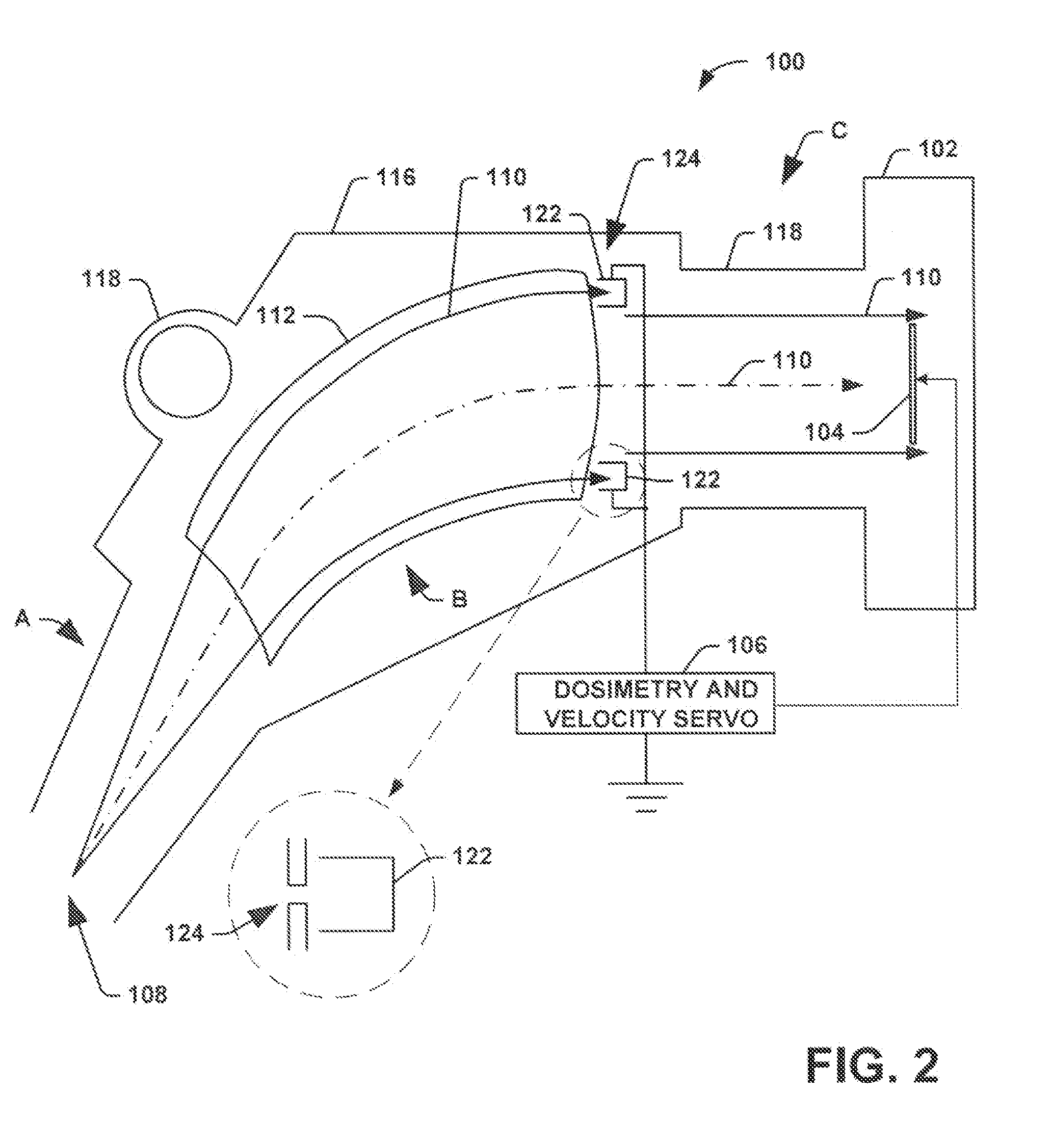
[0021]According to still another aspect of the invention, the end station resides in a process chamber having a vacuum pump operably associated therewith to achieve a vacuum therein. In addition, the beam bending element resides in a magnet chamber. The system also comprises a conductance limiter configured to couple together the process chamber and the magnet chamber that is further configured to reduce an influx of outgas from a workpiece on the end station into the magnet chamber.
[0024]According to another aspect of the invention, the method comprises scanning a pencil shaped beam into the ribbon shaped ion beam prior to bending the ribbon shaped ion beam, and selectively preventing the Faraday cup from registering a beam current measurement as a function of the scanning of the pencil shaped ion beam into the ribbon shaped ion beam. In one embodiment, selectively preventing comprises allowing the Faraday cup to register the beam current when the scanned ion beam sweeps across the Faraday cup, and preventing the Faraday cup from registering the beam current otherwise.
[0025]According to another aspect of the invention, the workpiece resides on an end station within a process chamber, and the beam bending element resides in a magnet chamber. In this instance the method comprises coupling the process chamber to the magnet chamber with a conductance limiter that is configured to reduce an influx of outgas from the workpiece into the magnet chamber.

Problems solved by technology

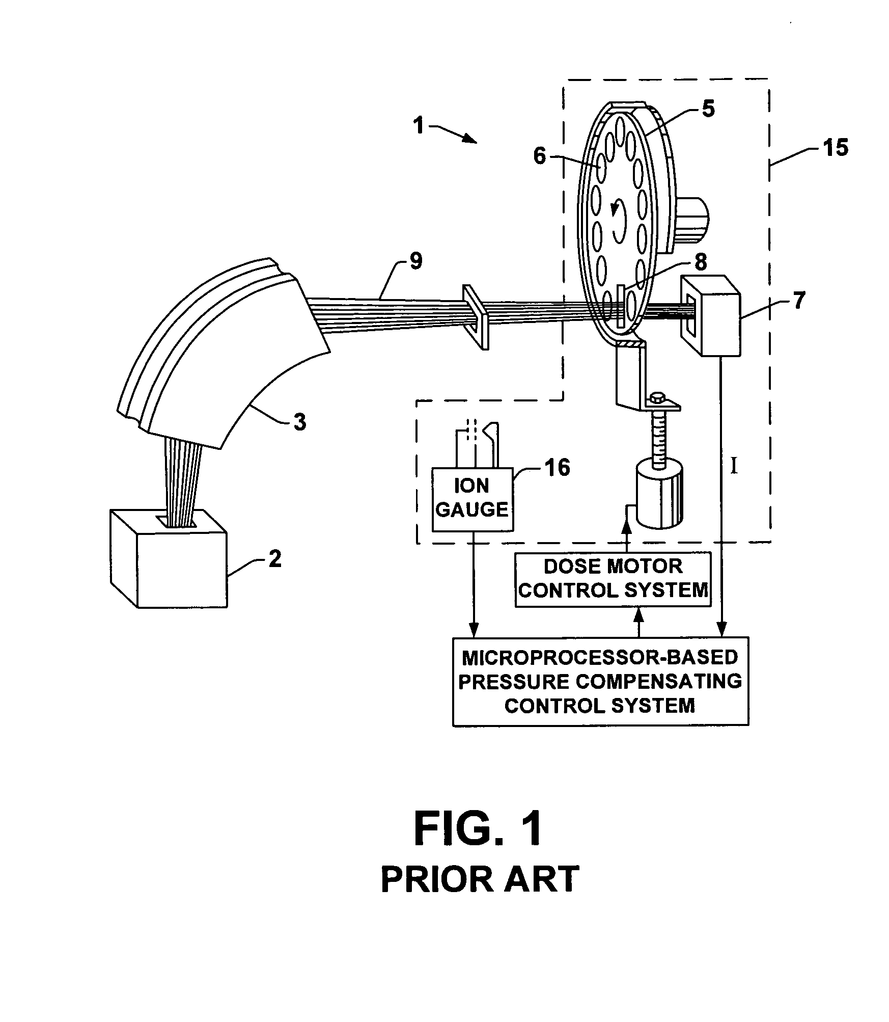
Since the charge state distribution of an ion beam can change (by charge exchange reactions which will be described in greater detail infra) and is very difficult to measure, especially since it may contain large portion of neutral atoms (which can not measured with any electrical methods), substantial effort is paid to keep the charge value in the ion beam at the initially intended single value.
One shortcoming of this p-comp method is that the empirical factor has to be determined on each implant recipe prior to actual implantation and effort has to be made so that the factor stays unchanged for long time.
Another challenge to this prior art solution is that the assumed functional approximation between a pressure and dose tends to break down at higher pressures.
Because of this challenge, some users limit beam current to keep the approximation valid although it affects the productivity adversely.

Method used


Image

  • System and method of performing uniform dose implantation under adverse conditions
  • System and method of performing uniform dose implantation under adverse conditions
  • System and method of performing uniform dose implantation under adverse conditions

Examples


Embodiment Construction

[0032]The present invention will now be described with reference to the drawings wherein like reference numerals are used to refer to like elements throughout. The invention provides a system and method for determining a pressure compensation factor for use in an ion implanter.

[0033]As stated above, charge exchange reactions between an ion beam and residual gas can add or subtract electrons from the ions, changing the various ions' charge state from the value stated in the recipe. When the charge exchange reaction is neutralization, a portion of the incident ion flux is neutralized. The result is a reduction in the detected electrical current while the actual particle current or flux (including neutrals) remains unchanged. When the charge exchange reaction is electron stripping, a portion of the ion flux loses electrons, and the result is an increase in the electrical current while the particle current remains the same.

[0034]For typical recipes where charge exchange is an issue, the...


PUM

PropertyMeasurementUnit
Angleaaaaaaaaaa
Currentaaaaaaaaaa
Electric potential / voltageaaaaaaaaaa

Abstract

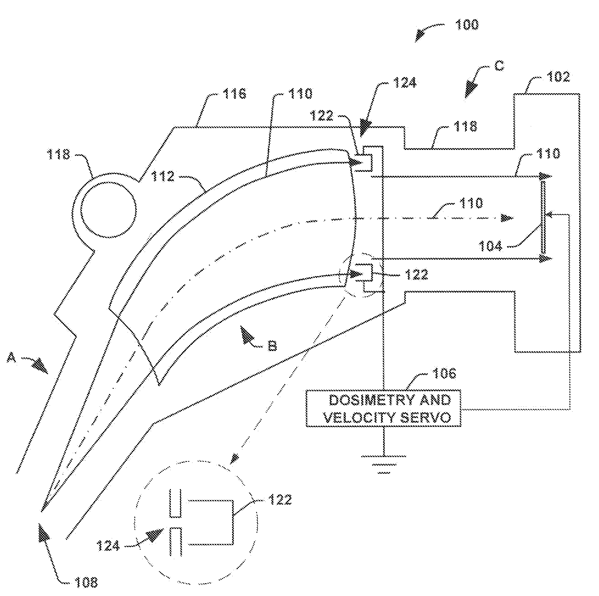
An ion implantation system and associated method includes a scanner configured to scan a pencil shaped ion beam into a ribbon shaped ion beam, and a beam bending element configured to receive the ribbon shaped ion beam having a first direction, and bend the ribbon shaped ion beam to travel in a second direction. The system further includes an end station positioned downstream of the beam bending element, wherein the end station is configured to receive the ribbon shaped ion beam traveling in the second direction, and secure a workpiece for implantation thereof. In addition, the system includes a beam current measurement system located at an exit opening of the beam bending element that is configured to measure a beam current of the ribbon shaped ion beam at the exit opening of the beam bending element.

Description

RELATED APPLICATION[0001]This application claims priority to and the benefit of Ser. No. 61 / 049,717 filed May 1, 2008, which is entitled “SYSTEM AND METHOD OF PERFORMING UNIFORM DOSE IMPLANTATION UNDER ADVERSE CONDITIONS”, the entirety of which is hereby incorporated by reference as if fully set forth herein.FIELD OF THE INVENTION[0002]The present invention relates generally to ion implantation systems, and more particularly to a system and method for performing dosimetry control under adverse conditions, for example, heavy outgassing during implants on photoresist coated workpieces / wafers.BACKGROUND OF THE INVENTION[0003]In the manufacture of semiconductor devices, ion implantation is used to dope semiconductors with impurities. Ion beam implanters are used to treat silicon wafers with an ion beam, in order to produce n or p type extrinsic material doping or to form passivation layers during fabrication of an integrated circuit. When used for doping semiconductors, the ion beam imp...

Claims


Application Information

Patent Timeline
IPC IPC(8): H01J37/08
CPCH01J37/244H01J37/304H01J37/3171H01J2237/24405H01J2237/31703H01J2237/24564H01J2237/30405H01J2237/30455H01J2237/24507
Inventor SATOH, SHU
Owner AXCELIS TECHNOLOGIES
Learn More