

Dielectric ceramic composition, multilayer complex electronic device, multilayer common mode filter, multilayer ceramic coil and multilayer ceramic capacitor
a technology of complex electronic devices and ceramics, applied in the direction of fixed capacitors, inductances, electrical devices, etc., can solve the problems of not being recommended, material having further low specific permittivity, and limiting the response to high frequency, etc., to achieve low dc resistance
- Summary
- Abstract
- Description
- Claims
- Application Information
AI Technical Summary
Benefits of technology
Problems solved by technology
Method used
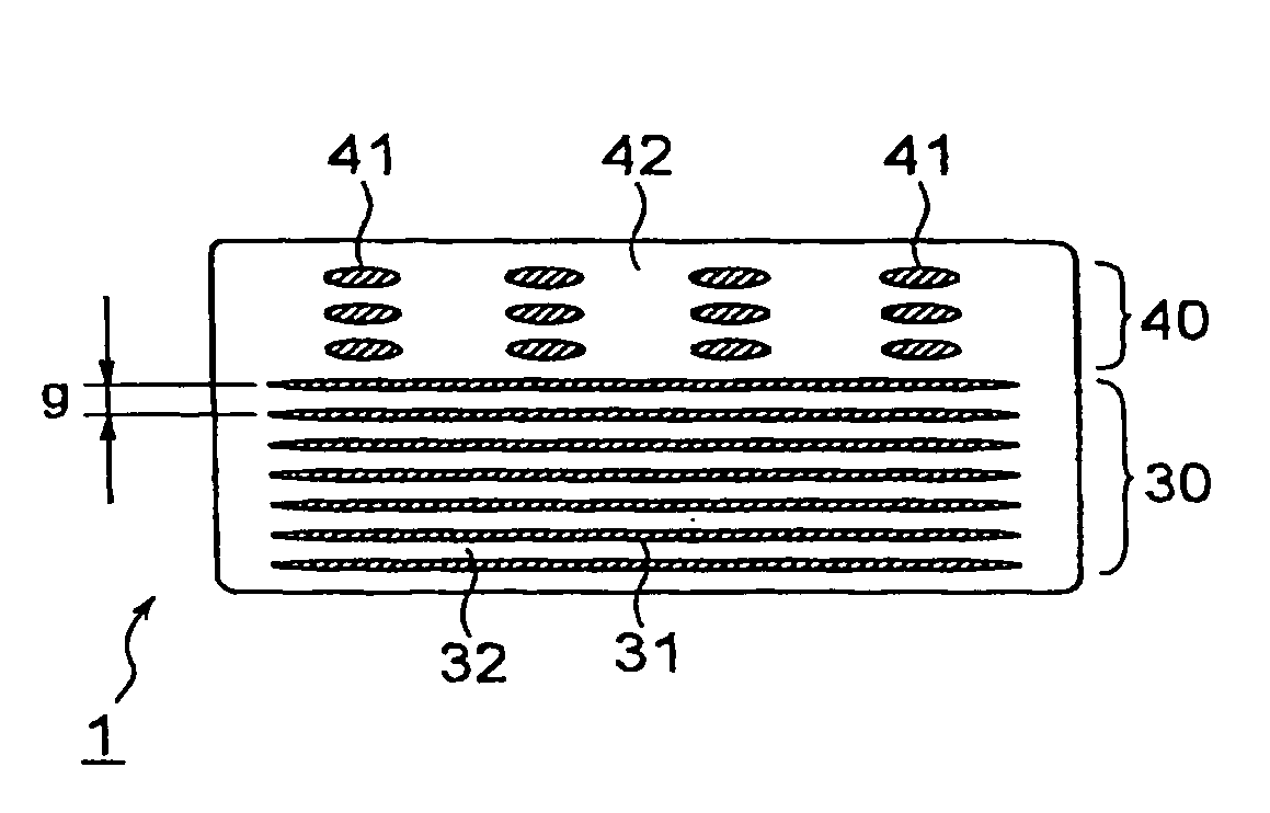
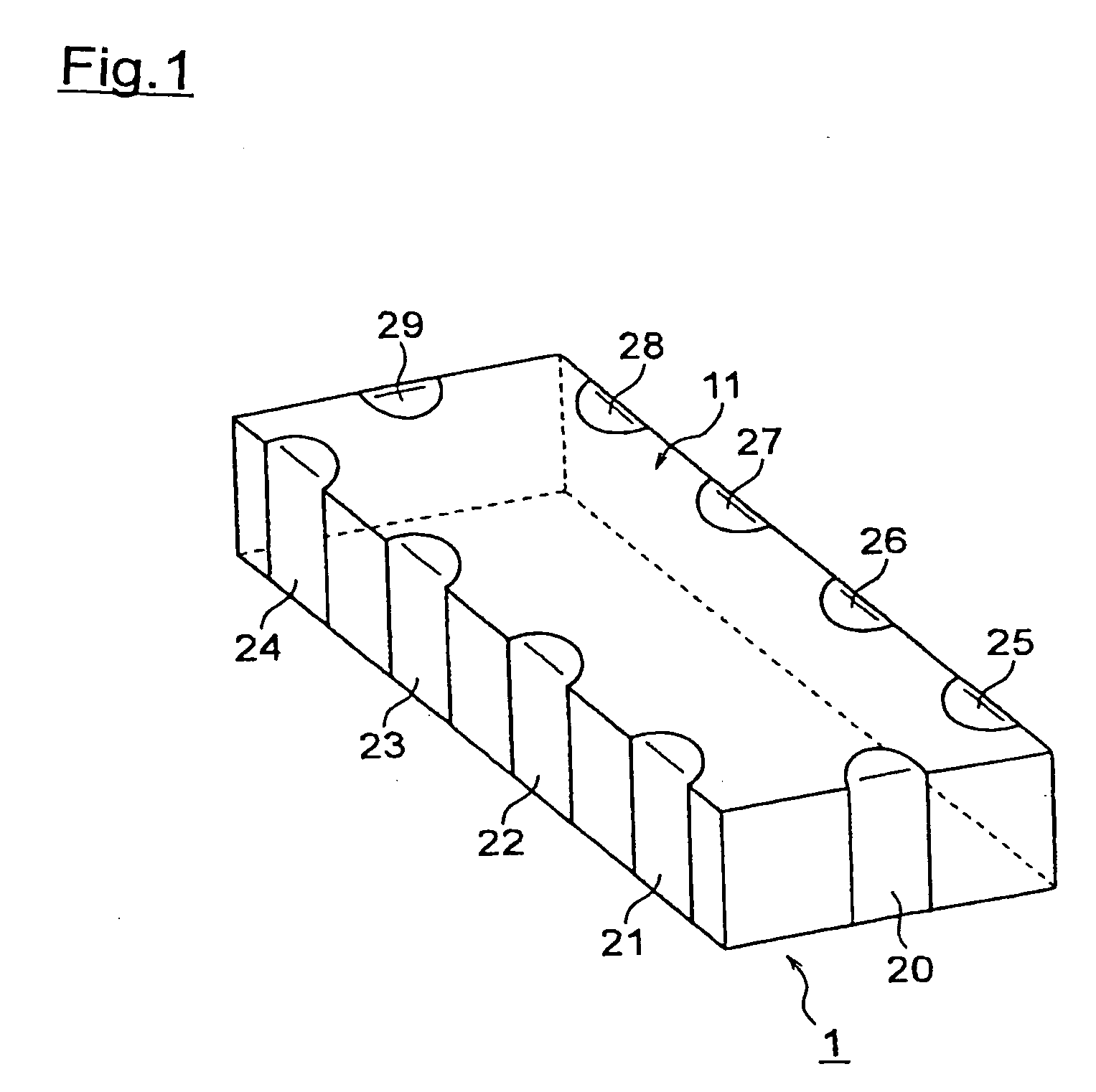
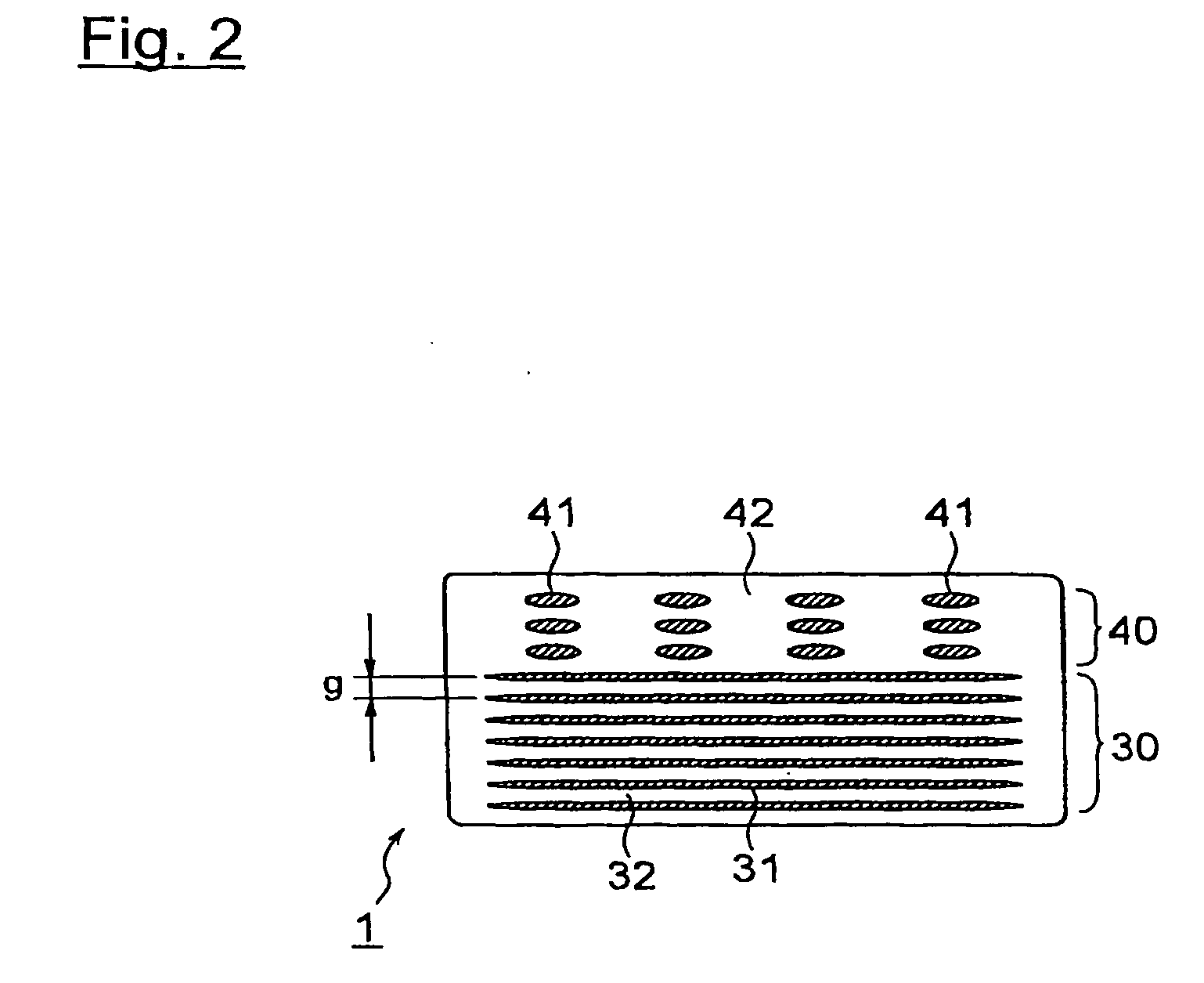
Image

Examples
example 1
[0119]First, MgO, ZnO, CuO, SiO2 as a main component material constituting a dielectric ceramic composition material and B2O3—SiO2—BaO—CaO-based glass as a subcomponent material was prepared. Note that, as the B2O3—SiO2—BaO—CaO-based glass, a commercial glass was used. And a glass softening point of the glass was 700° C.
[0120]Then, materials of the main components were weighed and compounded so that “a”, “b”, “c”, “d” in a general formula a(bMgO.cZnO.dCuO).SiO2 become values shown in Table 1 after sintering, and wet mixed by a ball mill for 24 hours. After wet mixing, the obtained slurry was dried by a dryer, followed by calcine at 1000° C. of the dried mixture of powders in a batch furnace to obtain a calcined powder. The B2O3—SiO2—BaO—CaO-based glass as a subcomponent material was added to the calcined powder, wet mixed by a ball mill for 16 hours, and the obtained slurry was dried by a dryer to obtain a material of a dielectric ceramic composition material according to the presen...
example 2
[0131]Except for changing the contents and the composition of the glass component to those shown in Table 2 and changing the “a”, “b”, “c” and “d” of the above described general formula to those shown in Table 2, a dielectric ceramic composition was produced as with Sample 1, and same evaluation was performed as in Example 1. The results are shown in Table 2. Note that, a glass softening point of the respective glass components are temperatures shown in Table 2.
TABLE 2subcomponentsintered body propertyglassmain componentcoefficientSam-soft-molespecificinsulationof linearpleeningratioMgOZnOCuOrelativepermittiveityresistance ρf · Qexpansion αNo.component(wt %)pointabcddencityε s(Ω· m)(GHz)(×10−7 / ° C.)11B2O3—SiO2—BaO4.06802.00.660.260.0896.4%6.971.5E+132140098.412B2O3—SiO2—CaO4.07202.00.660.260.0896.0%6.921.2E+131794598.613B2O3—SiO2—SrO4.07002.00.560.260.1897.8%7.151.5E+131843898.014B2O3—SiO2—Li2O4.06102.00.660.260.0898.9%7.341.0E+133024999.615B2O3—SiO2—BaO—CaO4.07002.00.660.260.0895.0...
example 3
[0135]Except for changing the “a”, “c”, “d” in the above described generic formula to those shown in Tables 3 to 5, a dielectric ceramic composition was produced as with Example 1, and same evaluation was performed as in Example 1. The results are shown in Tables 3 to 5.
TABLE 3main componentsintered body propertysubcomponentmolespecificinsulationcoefficient ofSampleglassratioMgOZnOCuOrelativepermittiveityresistance ρf · Qlinear expansion αNo.(wt %)abcddencityε s(Ω· m)(GHz)(×10−7 / ° C.)224.01.00.660.260.0853.9%3.913.0E+071754134.4234.01.30.660.260.0869.8%4.902.6E+073862116.9244.01.60.660.260.0890.1%6.922.0E+1223259104.3254.01.90.660.260.0894.1%7.085.9E+1226104103.5264.02.00.660.260.0895.0%7.175.9E+1226126101.9274.02.20.660.260.0896.1%7.273.3E+121752099.2284.02.40.660.260.0896.3%7.281.2E+1210498103.2294.02.50.660.260.0896.3%7.291.0E+128503104.5304.02.70.660.260.0895.0%7.203.5E+102485104.1in Table, (mE+n) means (m × 10+n)
TABLE 4main componentsintered body propertysubcomponentmolespecifi...
PUM
| Property | Measurement | Unit |
|---|---|---|
| glass softening point | aaaaa | aaaaa |
| softening point | aaaaa | aaaaa |
| temperature | aaaaa | aaaaa |
Abstract
Description
Claims
Application Information