Battery, electrode, and current collector used therefor

a current collector and battery technology, applied in the field of electrodes, can solve the problems of insufficient gap sealing inability to secure sufficient gaps in the active material layer, and inability to reduce the stress caused by the expansion and contraction of the active material, etc., to achieve excellent cycle performance, high capacity, and high reliability

Inactive Publication Date: 2009-11-12
PANASONIC INTELLECTUAL PROPERTY MANAGEMENT CO LTD
View PDF4 Cites 39 Cited by
  • Summary
  • Abstract
  • Description
  • Claims
  • Application Information

AI Technical Summary

Benefits of technology

[0052]By using a current collector of the present invention, the bonding area between the active material and the current collector becomes large. Therefore, bonding between the active material and the current collector becomes strong, and the active material separation from the current collector due to the expansion stress of the active material at the time of Li absorption is inhibited. Therefore, by using an electrode of the present invention, a highly reliable battery having a high capacity and excellent cycle performance can be obtained. The present invention is suitable particularly when using a high capacity active material (for example, a material containing Si element (Si-based material), and a material containing Sn element (Sn-based material)).
[0053]Furthermore, with the active material layer containing a plu

Problems solved by technology

Furthermore, in Patent Documents 3 and 4, since the gaps between the active material particles are formed naturally in the manufacturing step of the negative electrode, the gap pattern is not controlled.
Therefore, when silicon or tin which undergoes a very large degree of volume change involved with

Method used


Image

  • Battery, electrode, and current collector used therefor
  • Battery, electrode, and current collector used therefor
  • Battery, electrode, and current collector used therefor

Examples


embodiment 1

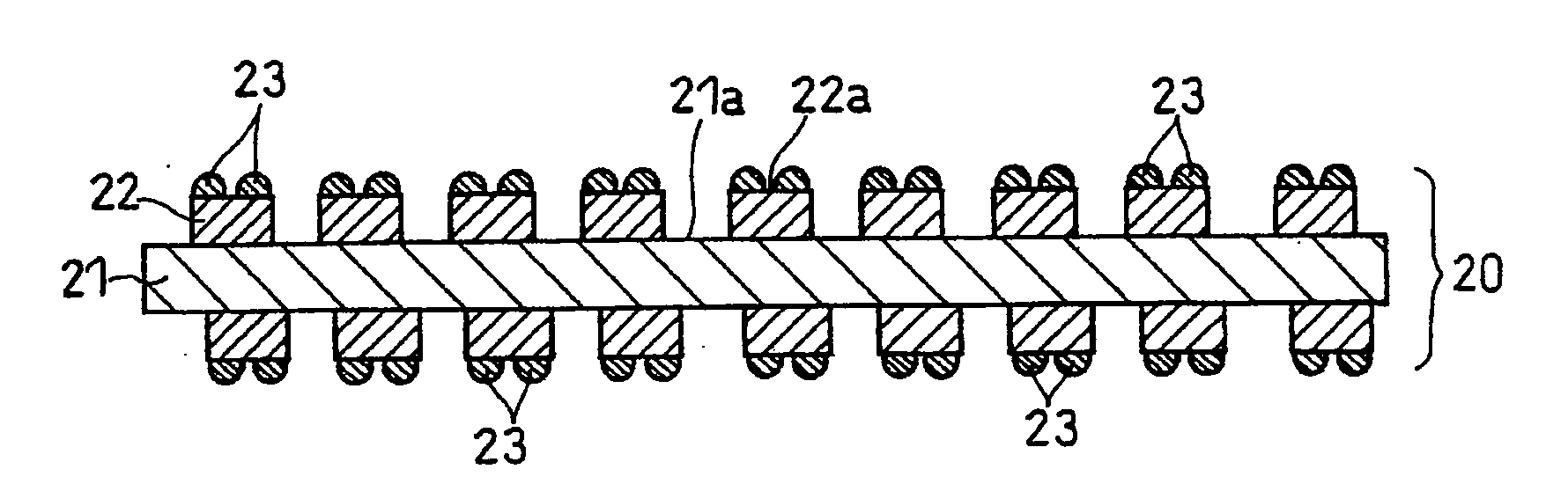
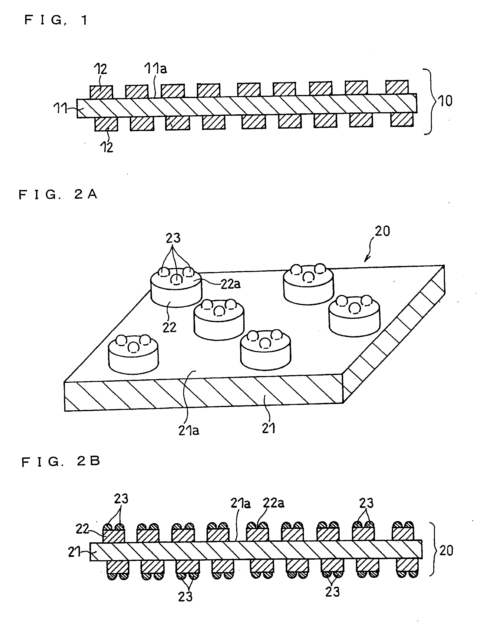
[0100]A current collector for an electrode of the present invention includes a base portion having a flat face, a plurality of primary projections projecting from the flat face, and a plurality of secondary projections projecting from the top of the primary projections. The base portion is integrated with the primary projections.

[0101]The base portion and the primary projections are formed simultaneously by, for example, deforming a sheet material (for example, a metal sheet). Also, a metal may also be deposited on the surface of a sheet material serving as the base portion, thereby forming the primary projections of the deposited metal.

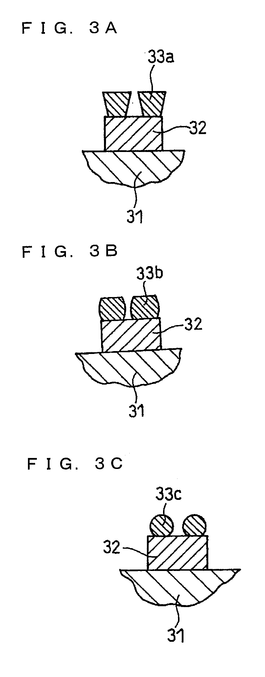
[0102]The secondary projections may be formed by any methods, including, for example, blasting, electrodeposition, plating, and etching.

[0103]When the base portion and the primary projections are formed simultaneously by deforming a metal sheet, the primary projections can be obtained by, for example, pressing the metal sheet with a roller having rec...

embodiment 2

[0285]A current collector for batteries in another embodiment of the present invention is described with reference to the figures.

[0286]FIG. 19 shows a current collector in another embodiment of the present invention. A current collector 140 in FIG. 19 includes a base portion 141 including a flat face, and primary projections 142 projecting from the flat face, and the roughening rate of the top of the primary projections 142 is 3 or more and 20 or less. In the current collector, the primary projections are preferably arranged regularly.

[0287]The roughening rate is described next. In the present invention, the roughening rate refers to the ratio of the surface area of a predetermined region of the top of the primary projections relative to the apparent area of the predetermined region. That is, the roughening rate is defined as, a surface area of a predetermined region of the top of the primary projections / apparent area of the region.

[0288]The surface area of a predetermined region o...

example 1-1

(i) Current Collector Preparation

First Step

[0311]A dry film resist with a thickness of 25 μm (manufactured by Hitachi Chemical Co., Ltd.) was attached on a rolled copper foil with a thickness of 18 μm, serving as a starting material.

[0312]A glass mask with a substantially diamond-shaped dot pattern was disposed on the dry film resist. Using a parallel exposure device, i-ray (ultraviolet ray having a wavelength of 365 nm) was applied over the mask to expose the resist. Afterwards, development was carried out by using an aqueous alkaline solution to form openings of a predetermined pattern on the resist. Then, copper was precipitated by plating on the substantially diamond-shaped openings thus formed. Afterwards, the resist was removed to obtain a sheet substrate having the substantially diamond-shaped primary projections. FIG. 21 is an electron micrograph of the surface of the obtained substrate. FIG. 22 is an electron micrograph showing a top oblique view of the same substrate.

[0313...


PUM


Abstract

The present invention relates to a current collector including a base portion with a flat face, primary projections projecting from the flat face, and secondary projections projecting from the top of the primary projections. The present invention also relates to a current collector including a base portion with a flat face and primary projections projecting from the flat face, wherein the roughening rate of the top of the primary projections is 3 to 20. By using such a current collector, separation of the active material from the current collector can be inhibited when using an active material that has a high capacity but undergoes a large expansion at the time of lithium ion absorption.

Description

RELATED APPLICATIONS[0001]This application is the U.S. National Phase under 35 U.S.C. § 371 of International Application No. PCT / JP2007 / 074890, filed on Dec. 26, 2007, which in turn claims the benefit of Japanese Application Nos. JP 2006-352768, filed on Dec. 27, 2006, JP 2007-120768, filed on May 1, 2007, JP 2007-128460, filed on May 14, 2007, JP 2007-156012, filed on Jun. 13, 2007, JP 2007-237715, filed on Sep. 13, 2007, and JP 2007-253199, filed on Sep. 28, 2007, the disclosures of which Applications are incorporated by reference herein.TECHNICAL FIELD[0002]The present invention relates to an electrode including a current collector and an active material carried on the current collector, and particularly relates to a current collector structure.BACKGROUND ART[0003]With recent development of portable devices such as a notebook personal computer and a mobile phone, there is an increasing demand for batteries used as a power source for those devices. The batteries used for these dev...

Claims


Application Information

Patent Timeline
IPC IPC(8): H01M4/02B05D5/12C25D5/00C25D5/10H01M4/134H01M4/1395H01M4/66H01M4/70
CPCH01M4/04H01M4/66H01M4/662Y02T10/7011H01M10/0525Y02E60/122H01M4/70Y02E60/10H01M4/02H01M4/38Y02T10/70Y02P70/50
Inventor ITO, SHUJIKOGETSU, YASUTAKAIWAMOTO, KAZUYAHONDA, KAZUYOSHIYAMAMOTO, TAISUKEUEYAMA, YASUHIROOHARA, KEISUKEKATAYAMA, HITOSHI
Owner PANASONIC INTELLECTUAL PROPERTY MANAGEMENT CO LTD
Why Eureka
Try Eureka