Wafer holder, manufacturing method thereof and semiconductor manufacturing apparatus
- Summary
- Abstract
- Description
- Claims
- Application Information
AI Technical Summary
Benefits of technology
Problems solved by technology
Method used
Image

Examples
working examples
Working Example 1
[0054]Yttrium oxide powder (0.5 wt %) was added as a sintering aid to aluminum nitride powder (99.5 wt %), an organic solvent and a binder were furthermore added, and the system was mixed using a ball mill to form a slurry. The resulting slurry was spray-dried to form granules, and a molded article was formed by press molding. The molded article was degreased at 800° C. in a nitrogen atmosphere and then sintered at 1,900° C. in a nitrogen atmosphere to obtain a sintered body made from aluminum nitride.
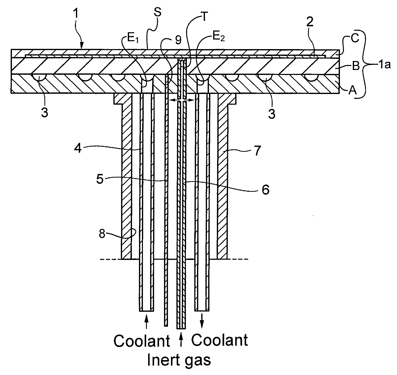
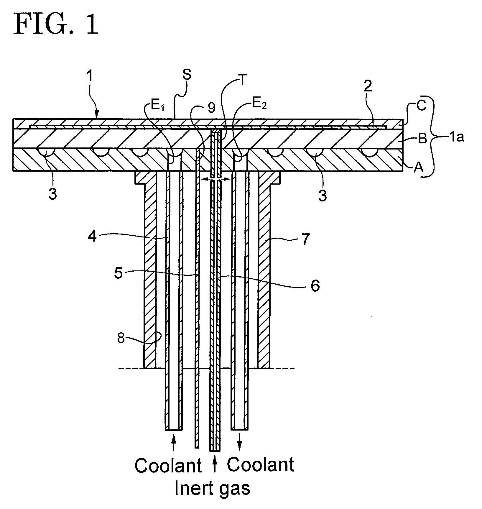
[0055]Three sintered bodies made from aluminum nitride were formed using the above method, and these sintered bodies were used as aluminum nitride substrates. Specifically, one of the sintered bodies was formed to a diameter of 330 mm and a thickness of 10 mm to form the substrate A, and thereafter machined to form a coolant flow channel 3 having a depth of 3 mm and a width of 6 mm. Since the diameter of the wafer to be mounted on the wafer holder 1 was 300 mm, the are...
working example 2
[0062]A flow channel 3 was formed in the aluminum nitride substrate A in the same manner as example 1 described above. In this case, the area for forming a flow channel 3 was varied for each example in the manner shown in TABLE 1 below, and the temperature distribution was measured for the case in which the temperature of the wafer holders was kept at 20° C. The results are shown in TABLE 1 below. The results of example 1 are also included in the table for reference. A wafer temperature gauge having a diameter of 300 mm and 29 measurement points was used to measure the temperature of the wafer.
TABLE 1Flow channel formation areaWafer temperatureOutermostRatio todistributionSamplediameter (mm)wafer (%)(−20° C. ±° C.)1 (Example 1)3101031.0023001001.053280931.154260871.205240801.256220731.557200671.95
working example 3
[0063]An aluminum nitride wafer holder 1 was fabricated in the same manner as example 1 described above. However, the surface roughness of the flow channel 3 was varied, a water-alcohol mixed solvent adjusted to a temperature of −10° C. was washed over the surface for 1,000 hours, and the corrosiveness of the aluminum nitride was confirmed by measuring the pH of the refrigerant after the test. Aluminum nitride is ordinarily relatively stable in atmosphere because an oxide-based film is formed on the surface, but ammonia is generated when moisture makes contact with broken surfaces, polished surfaces, and other portions on which a film is not formed. It was therefore determined that corrosion of the flow channel 3 progresses when the pH is an alkaline pH. The results are shown in TABLE 2 below. The pH prior to testing was 7 in all cases.
TABLE 2Surface roughness ofRefrigerant pHthe flow channel (Ra: μm)after testing0.57.51.07.61.57.82.17.92.68.03.28.13.88.14.38.25.08.35.89.56.511.2
PUM
| Property | Measurement | Unit |
|---|---|---|
| Time | aaaaa | aaaaa |
| Dew point | aaaaa | aaaaa |
| Fraction | aaaaa | aaaaa |
Abstract
Description
Claims
Application Information
 - Generate Ideas
- Intellectual Property
- Life Sciences
- Materials
- Tech Scout
- Unparalleled Data Quality
- Higher Quality Content
- 60% Fewer Hallucinations
Browse by: Latest US Patents, China's latest patents, Technical Efficacy Thesaurus, Application Domain, Technology Topic, Popular Technical Reports.
© 2025 PatSnap. All rights reserved.Legal|Privacy policy|Modern Slavery Act Transparency Statement|Sitemap|About US| Contact US: help@patsnap.com