Graphene-based structure, method of suspending graphene membrane, and method of depositing material onto graphene membrane

a graphene and membrane technology, applied in the field of graphene, can solve the problems of requiring not only novel materials but also means, and difficult to achieve the degree of control of nanotubes, and achieve the effect of reducing the number of nanotubes, and reducing the cost of production

Active Publication Date: 2009-11-26
RGT UNIV OF CALIFORNIA
View PDF6 Cites 136 Cited by
  • Summary
  • Abstract
  • Description
  • Claims
  • Application Information

AI Technical Summary

Problems solved by technology

This is partly because it can be patterned into arbitrary shapes by lithographic means which readily provides a degree of control difficult to achieve with nanotubes.
Nevertheless, smaller devices require not only novel materials but also a means of shaping those materials into a tiny circuit.
State of the art, resist based, electron beam lithography (EBL) methods, notwithstanding throughput issues, rarely achieve a half-pitch of less than 20 nm on bulk substrates.
Although electron beams can be focused to sub-angstrom diameters, scattered and secondary electrons generated in a bulk substrate and resist limit the modulation in the energy profile that can ultimately realized.
Accordingly, the smallest feature sizes using EBL having not improved significantly over the last three decades.
While there is the existing technique for producing suspended graphene that is discussed above, it is complicated and consequently expensive.
However, a new form of lithography is needed to make extremely small devices on graphene.

Method used


Image

  • Graphene-based structure, method of suspending graphene membrane, and method of depositing material onto graphene membrane
  • Graphene-based structure, method of suspending graphene membrane, and method of depositing material onto graphene membrane
  • Graphene-based structure, method of suspending graphene membrane, and method of depositing material onto graphene membrane

Examples


example 1

Method of Suspending a Graphene Membrane

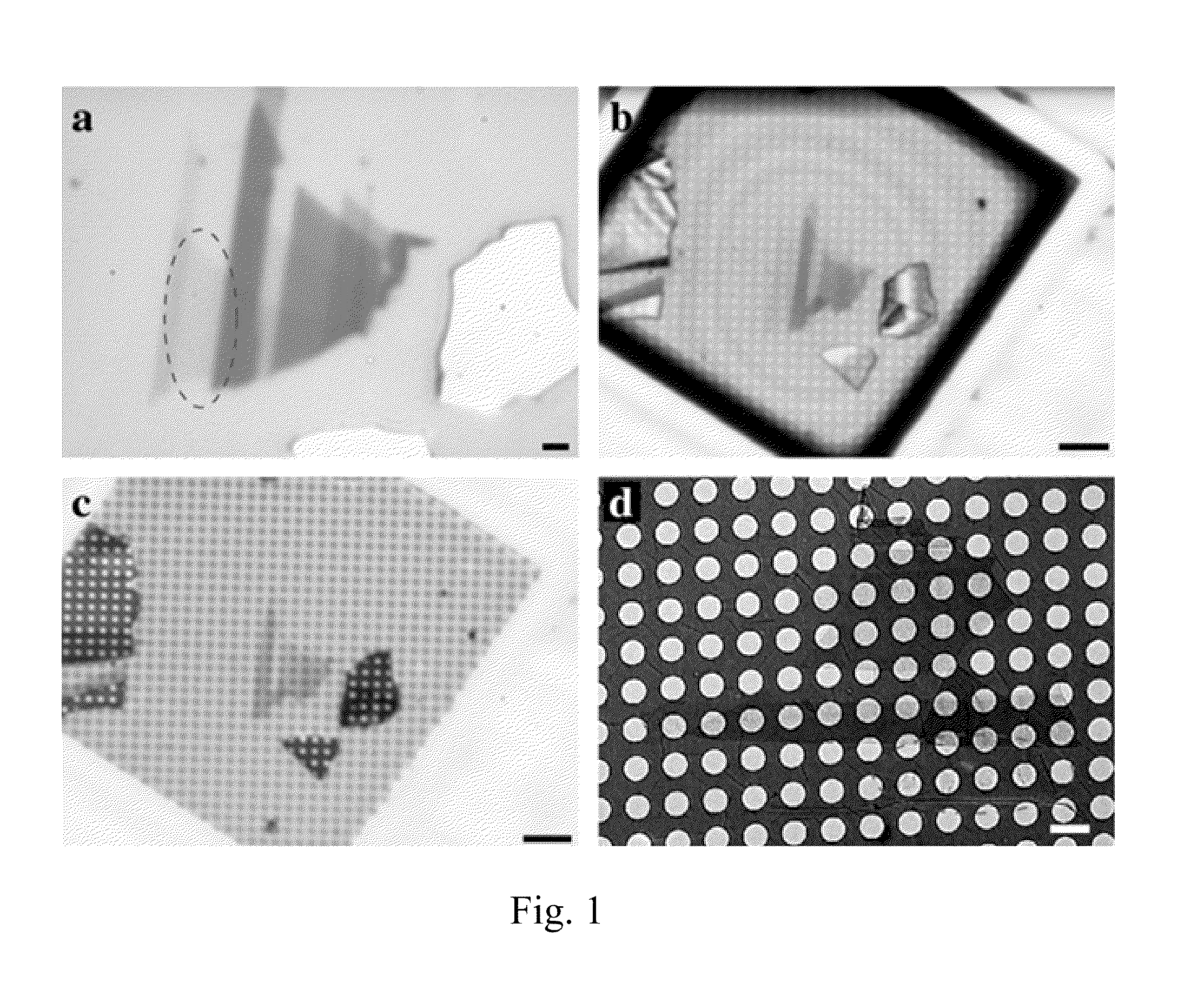
[0058]Our experimental procedure begins with graphene flakes made by the established “scotch tape” method. In order to suspend graphene membranes, we have developed transfer processes of the graphene flakes to commercially available electron microscopy grids (Quantifoil 200 Mesh gold grids with 1.3 μm holes in the carbon film). In the first method, we start with graphene flakes on a silicon substrate with a 300 nm silicon dioxide layer. We identify graphene flakes by optical microscopy (FIG. 1, Panel a), and place the Quantifoil grid onto the flake. A small drop of isopropanol is added (FIG. 1, Panel b) and left to evaporate. The surface tension of this solvent during evaporation pulls the perforated carbon film into contact with the substrate and graphene flakes (FIG. 1, Panel c). To improve the adhesion, we now heat the sample on a hot plate at 200° C. for 5 minutes. After cooling, we place the substrate with the now well-sticking TEM grid i...

example 2

Method of Suspending a Graphene Membrane

[0059]In another method, we begin with graphene flakes prepared on silicon substrates with a 300 nm silicon dioxide layer and a 10-30 nm layer of polymethylmetacrylate (PMMA). Again, the Quantifoil TEM grid is placed onto the flakes and pulled into contact with the surface by evaporation of a solvent (isopropanol). Contact is improved by heating on a hot plate. The top layer of the substrate is now dissolved in a bath of acetone or methylpyrrolidone. After separating the TEM grid with the graphene flakes from the substrate, it is again transferred to isopropanol before drying. This second method avoids the use of acids or bases (such as potassium hydroxide).

[0060]Just before insertion into the TEM, the graphene membrane samples are again heated on a hot plate to reduce the amount of adsorbates that are present on the sample surface due to the wet preparation and due to air exposure. For the results shown here, samples were heated for 10 minute...

example 3

Imaging and Dynamics of Carbon and Hydrogen Atoms on Graphene

[0064]Observing the individual building blocks of matter is one of the primary goals of microscopy. The invention of the scanning tunneling microscope revolutionized experimental surface science in that atomic-scale features on a solid-state surface could finally be readily imaged. However, scanning tunneling microscopy has limited applicability due to restrictions, for example, in sample conductivity, cleanliness, and data acquisition rate. An older microscopy technique, that of transmission electron microscopy (TEM) has benefited tremendously in recent years from subtle instrumentation advances, and individual heavy (high atomic number) atoms can now be detected by TEM even when embedded within a semiconductor material. However, detecting an individual low atomic number atom, for example carbon or even hydrogen, is still extremely challenging, if not impossible, via conventional TEM due to the very low contrast of light ...


PUM

PropertyMeasurementUnit
diametersaaaaaaaaaa
thicknessaaaaaaaaaa
thicknessaaaaaaaaaa

Abstract

An embodiment of a method of suspending a graphene membrane across a gap in a support structure includes attaching graphene to a substrate. A pre-fabricated support structure having the gap is attached to the graphene. The graphene and the pre-fabricated support structure are then separated from the substrate which leaves the graphene membrane suspended across the gap in the pre-fabricated support structure. An embodiment of a method of depositing material includes placing a support structure having a graphene membrane suspended across a gap under vacuum. A precursor is adsorbed to a surface of the graphene membrane. A portion of the graphene membrane is exposed to a focused electron beam which deposits a material from the precursor onto the graphene membrane. An embodiment of a graphene-based structure includes a support structure having a gap, a graphene membrane suspended across the gap, and a material deposited in a pattern on the graphene membrane.

Description

RELATED APPLICATIONS[0001]This application claims priority to and the benefit of U.S. Provisional Application No. 61 / 039,002, filed on Mar. 24, 2008, which is hereby incorporated by reference.STATEMENT OF GOVERNMENTAL SUPPORT[0002]This invention was made with government support under Contract No. DE-AC02-05CH11231 awarded by the U.S. Department of Energy. The government has certain rights in this invention.FIELD OF THE INVENTION[0003]This invention relates generally to graphene.BACKGROUND OF THE INVENTION[0004]Graphene is a single planar sheet of sp3-bonded carbon atoms that are densely packed in a honeycomb crystal lattice and which was first isolated in 2004. The carbon-carbon bond length in graphene is approximately 1.42 Å. Since the experimental verification the following year of many of its theoretically predicted electronic properties, single- and few-layer graphene has been suggested as a promising candidate material for future microelectronic devices. Graphene is in many res...

Claims


Application Information

Patent Timeline
Patent Type & Authority Applications(United States)
IPC IPC(8): B44C1/16B32B3/10B44C1/22C23C14/30
CPCB81B2203/0127B81C99/008B81C2201/0191Y10T428/24562B01D71/021Y10T428/24802H01J37/20B01D71/0211B01D71/0212
Inventor ZETTL, ALEXANDER K.MEYER, JANNIK CHRISTIAN
Owner RGT UNIV OF CALIFORNIA
Why Eureka
Try Eureka