Gas turbine integrated with fuel catalytic partial oxidation

Active Publication Date: 2009-12-03
ANSALDO ENERGIA SWITZERLAND AG
View PDF6 Cites 11 Cited by
  • Summary
  • Abstract
  • Description
  • Claims
  • Application Information

AI Technical Summary

Benefits of technology

[0007]In yet another embodiment, a method of removing carbon dioxide from a fuel/air mixture is provided in which a supply of compressed air is directed from a plenum into a premixer where it is mixed with a supply of natural gas to produce a fuel/air mixture. The fuel/air mixture is then directed into a CPOX reactor where the hydrocarbons in the fuel/air mixture are partially-oxidized to form carbon monoxide and hydrogen. The fuel/air mixture is then directed towards a shift reac

Problems solved by technology

While natural gas combined cycle power plants offer one of the cleanest alternatives fo

Method used


Image

  • Gas turbine integrated with fuel catalytic partial oxidation
  • Gas turbine integrated with fuel catalytic partial oxidation
  • Gas turbine integrated with fuel catalytic partial oxidation

Examples


Embodiment Construction

[0014]The subject matter of the present invention is described with specificity herein to meet statutory requirements. However, the description itself is not intended to limit the scope of this patent. Rather, the inventors have contemplated that the claimed subject matter might also be embodied in other ways, to include different components, combinations of components, steps, or combinations of steps similar to the ones described in this document, in conjunction with other present or future technologies.

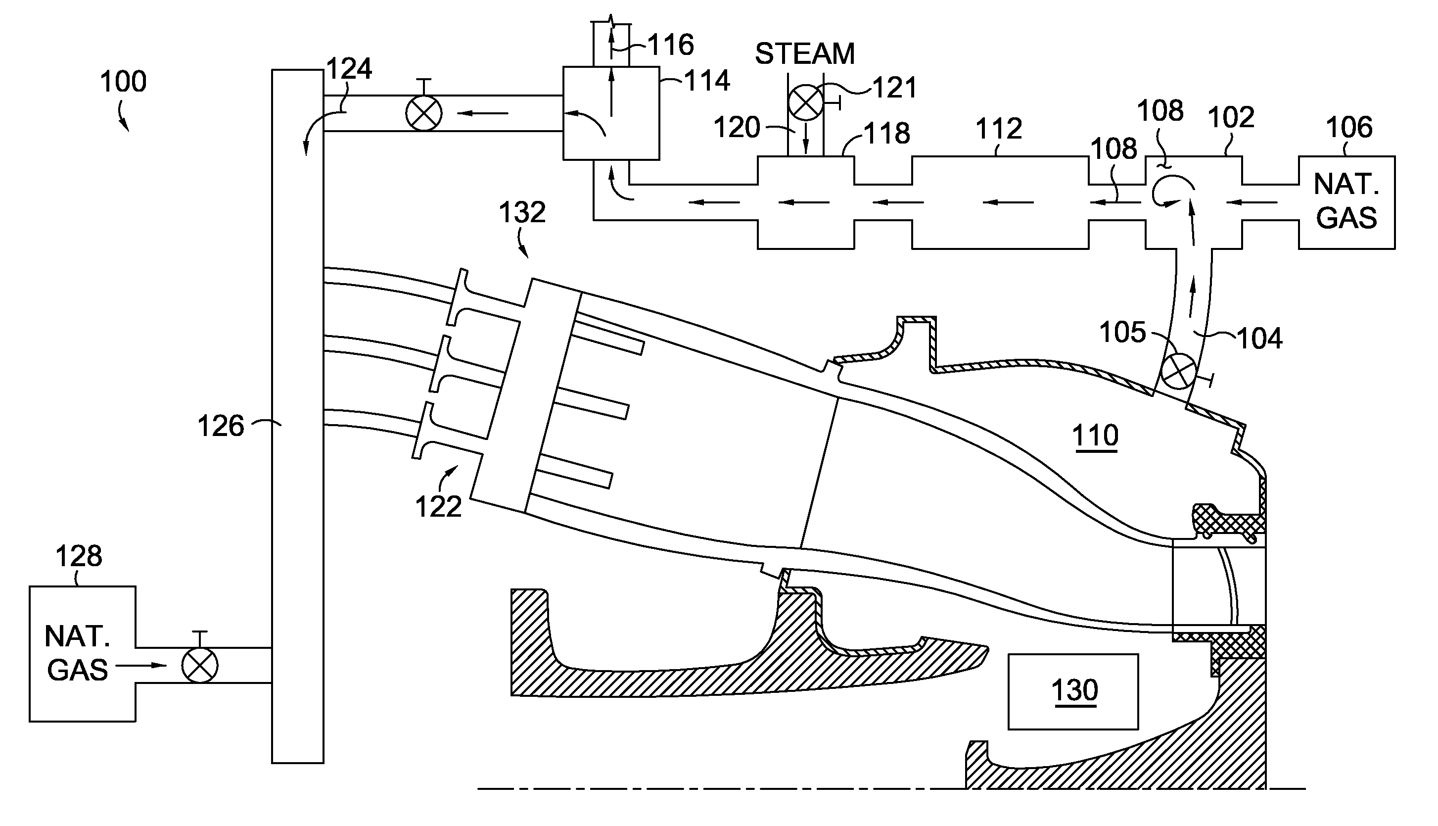
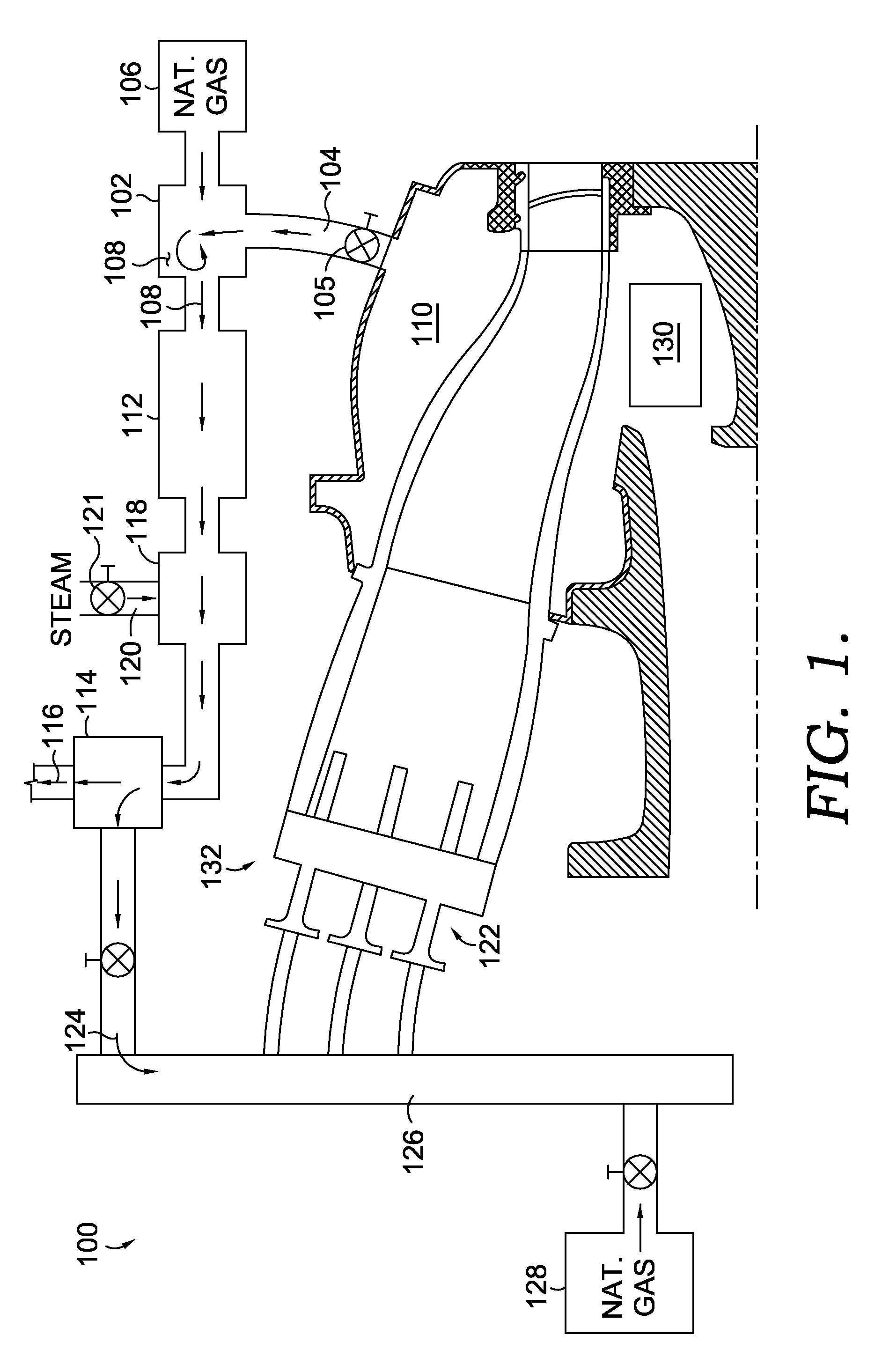
[0015]Embodiments of the present invention are depicted in FIGS. 1-4. Referring initially to FIG. 1, a system 100 capable of reducing carbon dioxide in a fuel / air mixture is disclosed in conjunction with a combined cycle gas turbine engine. The system of FIG. 1 displays in an engine pictorial layout with a premixer 102 that receives an air supply 104 that is permitted into the premixer 102 by a variable valve 105. In the premixer 102, the air supply 104 mixes with a supply of natura...


PUM


Abstract

A system and method for removing at least carbon from a fuel/air mixture prior to injection of the fuel/air mixture into a combustion system is disclosed. The system fully integrates the combined cycle power plant with carbon scrubbing of the fuel/air mixture to increase overall cycle efficiency while capturing carbon from the cycle. A portion of the compressed air source generated by the gas turbine compressor is provided to a premixer where it is mixed with a natural gas to form a fuel/air mixture. The fuel/air mixture passes through a catalytic partial oxidation (CPOX) reactor, which utilizes a precious metal to partially oxidize the hydrocarbons into carbon monoxide. The mixture passes through a shift reactor to complete generation of carbon dioxide and raise hydrogen yield of the fuel/air mixture. Carbon constituents are then removed from the mixture by a separator.

Description

CROSS-REFERENCE TO RELATED APPLICATIONS[0001]Not applicable.TECHNICAL FIELD[0002]The present invention relates to gas turbine engines. More particularly, embodiments of the present invention relate to a system and method for removing carbon dioxide from a hydrocarbon air mixture.BACKGROUND OF THE INVENTION[0003]Gas turbine engines operate to produce mechanical work or thrust. Specifically, land-based gas turbine engines typically have a generator coupled thereto for the purposes of generating electricity. A gas turbine engine comprises an inlet that directs air to a compressor section, which has stages of rotating compressor blades. As the air passes through the compressor, the pressure of the air increases. The compressed air is then directed into one or more combustors where fuel is injected into the compressed air and the mixture is ignited. The hot combustion gases are then directed from the combustion section to a turbine section by a transition duct. The hot combustion gases c...

Claims


Application Information

Patent Timeline
IPC IPC(8): F02B43/00
CPCF02C3/20F05D2240/36Y02E20/16F02C3/28
Inventor STUTTAFORD, PETER JOHN
Owner ANSALDO ENERGIA SWITZERLAND AG
Why Eureka
Try Eureka