Transient compressor surge response for a turbocharged engine

a turbocharged engine and compressor technology, applied in combustion engines, machines/engines, electric control, etc., can solve the problems of poor response and emissions characteristics, undesirable stresses in the turbocharger and the intake, and the turbocharger compressor coupled to the internal combustion engine may be subject to unwanted surge, etc., to increase the power output of the internal combustion engine, increase the mass of air, and increase the effect of power

Active Publication Date: 2009-12-03
FORD GLOBAL TECH LLC
View PDF12 Cites 30 Cited by
  • Summary
  • Abstract
  • Description
  • Claims
  • Application Information

AI Technical Summary

Benefits of technology

[0003]A turbocharger may be used to increase the power output of an internal combustion engine. The turbocharger does so by pressurizing the intake air, thereby increasing the mass of air provided to each of the engine's combustion chambers during the intake stroke. The increased air mass supports combustion of a correspondingly greater amount of fuel delivered to each combustion chamber, which provides increased power relative to a naturally aspirated engine of similar displacement. In a motor vehicle, a turbocharged engine may provide increased fuel economy by mai...

Problems solved by technology

Proper sizing of the operating net is required to meet the attributes of the engine: making the operating net too large may result in poor response and emissions characteristics, for example.
However, a turbocharger compressor coupled to an internal combustion engine may be subject to unwanted surge when a pressure ratio in the turbocharger compressor (viz., P, the ratio of the outlet pressure to the inlet pressure) is too great relative to the flow of air through the turbocharger compressor.
Turbocharger compressor surge (TCS) is a dynamic instability mode that can generate air-flow and pressure oscillations of great amplitude; this condition may induce undesirable stresses in the turbocharger and the intake, including excessive torsional loading on the turbocharger shaft.
Continued or excessive TCS may decrease the longevity of the turbocharger and/o...

Method used


Image

  • Transient compressor surge response for a turbocharged engine
  • Transient compressor surge response for a turbocharged engine
  • Transient compressor surge response for a turbocharged engine

Examples


Embodiment Construction

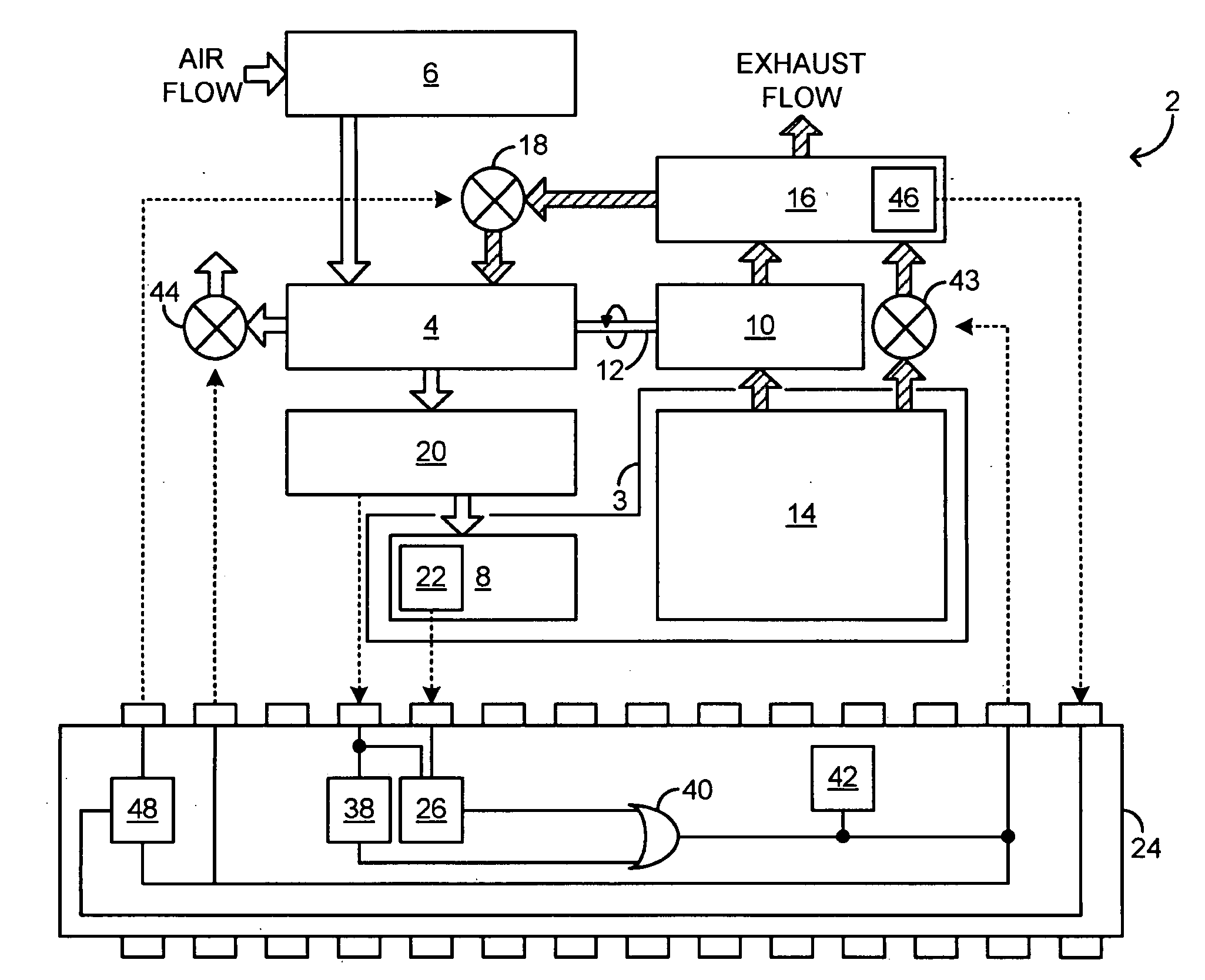
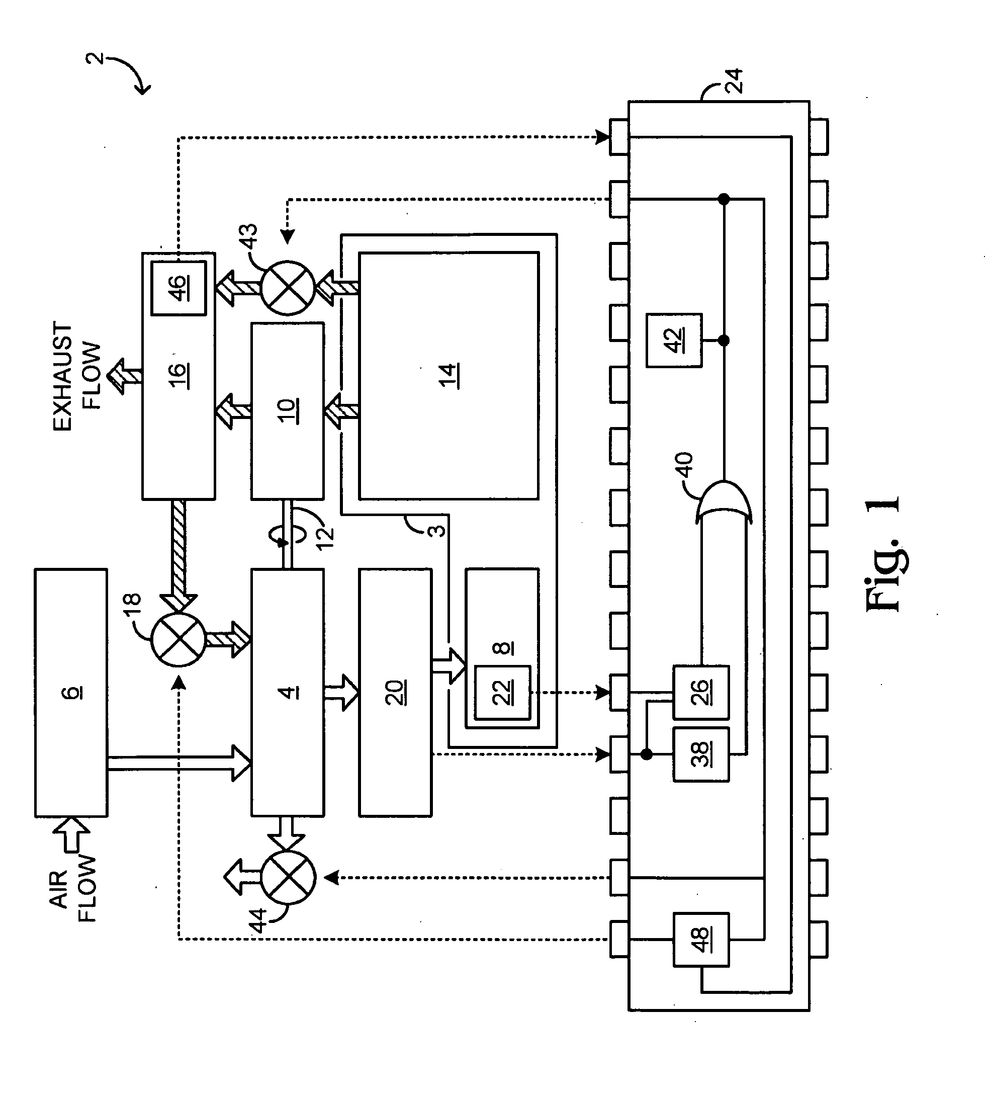
[0015]FIG. 1 shows in schematic detail an example engine system 2 including and engine 3, which may be disposed in a motor vehicle. The engine system includes turbocharger compressor 4, which is configured to draw air from air cleaner 6 and to provide pressurized air to intake manifold 8. The turbocharger compressor is mechanically coupled to and driven by turbocharger turbine 10 via shaft 12. The turbocharger turbine derives mechanical power from hot engine exhaust conducted therethrough. Accordingly, turbocharger turbine 10 is configured to admit engine exhaust from exahaust manifold 14, and to route the engine exhaust (at a lower temperature and pressure) to exhaust passage 16.

[0016]Engine system 2 further includes exhaust-gas recirculation (EGR) valve 18, which is an electronically controllable valve configured to controllably admit engine exhaust from the exhaust passage to turbocharger compressor 4. Thus, the illustrated engine system embodies a so-called ‘low-pressure EGR’ st...


PUM


Abstract

A method for responding to an existing or incipient surge condition of a turbocharger coupled to an engine of a motor vehicle is provided. The method comprises receiving a signal responsive to an operating condition of the turbocharger and adjusting one or more operating parameters of the motor vehicle when a power of the signal, integrated over a pre-selected range of non-zero frequencies, exceeds a pre-selected threshold. Other embodiments provide related systems for responding to an existing or incipient surge condition of a turbocharger.

Description

CROSS REFERENCE TO RELATED APPLICATION[0001]This application claims the benefit of U.S. Provisional Application 61 / 056,620, filed on May 28, 2008, and entitled METHOD OF TRANSIENT COMPRESSOR SURGE DETECTION FOR A TURBOCHARGED INTERNAL COMBUSTION ENGINE, the entirety of which is hereby incorporated herein by reference for all purposes.TECHNICAL FIELD[0002]The present application relates to the field of internal combustion engines, and more particularly, to improving the reliability of turbocharged internal combustion engines of motor vehicles.BACKGROUND AND SUMMARY[0003]A turbocharger may be used to increase the power output of an internal combustion engine. The turbocharger does so by pressurizing the intake air, thereby increasing the mass of air provided to each of the engine's combustion chambers during the intake stroke. The increased air mass supports combustion of a correspondingly greater amount of fuel delivered to each combustion chamber, which provides increased power rela...

Claims


Application Information

Patent Timeline
IPC IPC(8): F02D23/00
CPCF02B39/16F02D41/0007F02D41/005F02D41/0072Y02T10/47F02D2041/1432F02D2200/0406Y02T10/144F02D41/187Y02T10/12Y02T10/40
Inventor SHU, YONGVAN NIEUWSTADT, MICHIEL J.FULTON, BRIEN LLOYDKORPICS, FRANK M.SUN, HAROLD HUIMIN
Owner FORD GLOBAL TECH LLC
Why Eureka
Try Eureka