
Method of producing semiconductor device

Active Publication Date: 2009-12-03
FUJI ELECTRIC CO LTD
View PDF33 Cites 14 Cited by
  • Summary
  • Abstract
  • Description
  • Claims
  • Application Information

AI Technical Summary

Benefits of technology

[0009]The invention provides an efficient semiconductor device producing method for forming a device surface structure in a desired position of a surface layer of a semiconductor substrate in production of a semiconductor device having a super junction structure. The invention further provides a semiconductor device producing method which can reduce defects produced in an epitaxial layer when a super junction structure region is formed in a semiconductor device.
[0012]According to the invention, an alignment marker can be formed easily concurrently with the formation of the junction structure of alternate arrangement of the first conductivity type semiconductor and the second conductivity type semiconductor. For this reason, it is unnecessary to provide any additional step only for the formation of the alignment marker in the ordinary MOSEFT producing process. Accordingly, improvement in efficiency of the producing process can be attained. Moreover, because the lower limit of the width of the second trench is 1.6 times as large as the width of the first trench, the upper end portion of the second trench not filled with the second conductivity type semiconductor remains as an alignment marker even when the first trench is filled with the second conductivity type semiconductor in the condition that the mask is removed fully. Accordingly, the alignment marker can be recognized accurately. For this reason, the mask can be removed fully before the first trench is filled with the second conductivity type semiconductor. Accordingly, defects produced in the epitaxial layer by the influence of stress of the mask can be reduced. Moreover, because the upper limit of the width of the second trench is 2.5 times as large as the width of the first trench, black silicon can be prevented from being produced in the second trench during etching. In addition, foreign matter such as pieces of the removed resist film or particles can be removed easily even when the foreign matter is deposited on the inside of the second trench in a post step. Accordingly, a trench etching process without etching defects can be achieved, so that device characteristic can be prevented from deteriorating. Moreover, the surface structure of the device can be aligned accurately.
[0013]In the semiconductor device producing method according to the invention, producing efficiency can be improved in production of a semiconductor device having a super junction structure. Moreover, defects produced in the epitaxial layer formed on the semiconductor substrate can be reduced.

Problems solved by technology

When the epitaxial layers are grown in a state where the mask oxide film remains, there is a possibility that defects may be produced in the epitaxial layers of the p-type semiconductor region and the n-type semiconductor region by stress of the mask oxide film.
There is a possibility that the defects may be a cause of occurrence of a leakage current.

Method used


Image

  • Method of producing semiconductor device
  • Method of producing semiconductor device
  • Method of producing semiconductor device

Examples


Embodiment Construction

[0026]In this specification and the accompanying drawings, the prefix ‘n’ or ‘p’ attached to a layer or region means that electrons or holes are majority carriers. The superscript ‘+’ attached to the prefix ‘n’ means that the impurity concentration of the layer or region is higher than that of a layer or region having no superscript ‘+’ Incidentally, in the following description of embodiment and the accompanying drawings, like numerals refer to like constituent parts for the sake of avoidance of duplicate description.

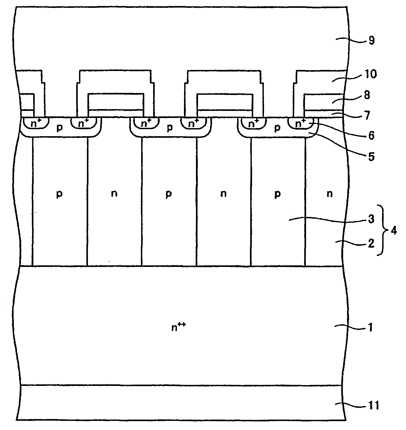
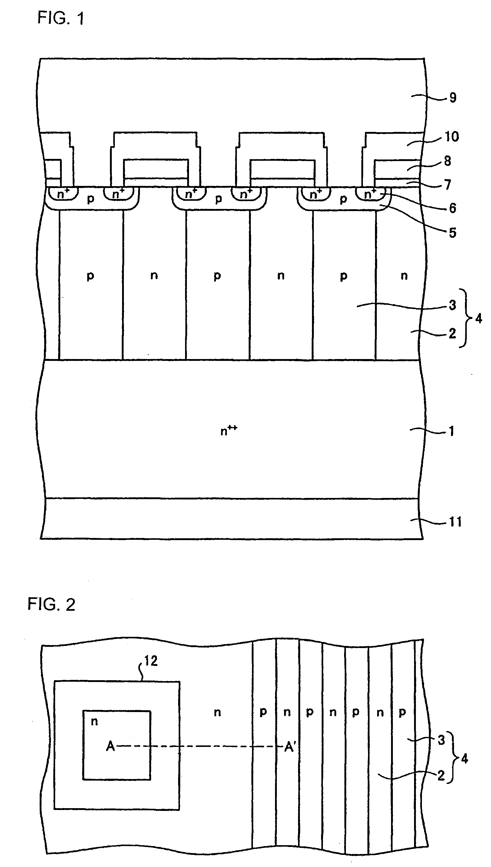
[0027]FIG. 1 is a sectional view showing an example of a super junction semiconductor device produced by a producing method according to the invention. Description will be made in the case where a vertical MOSFET is used as an example. As shown in FIG. 1, a parallel pn structure 4 in which n-type semiconductor regions 2 and p-type semiconductor regions 3 are joined alternately is provided on a low resistance n++ drain layer 1. A high impurity concentration p base regio...


PUM


Abstract

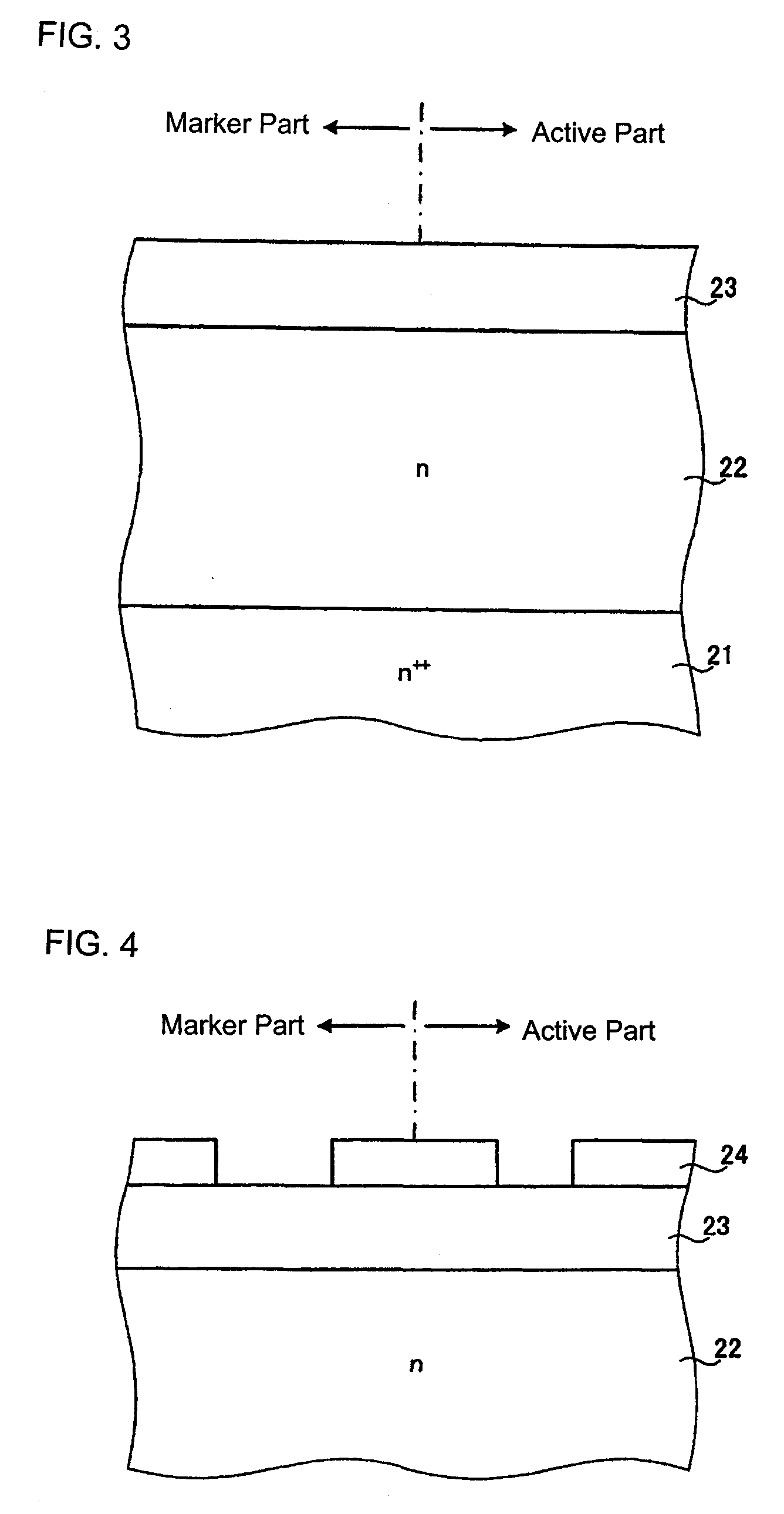
A semiconductor device is manufactured by forming a mask having a first opening and a second opening wider than the first opening on a principal surface of a first conductivity type semiconductor substrate, etching semiconductor portions of the first conductivity type semiconductor substrate exposed in the first and second openings to thereby form a first trench in the first opening and form a second trench deeper than the first trench in the second opening, and filling the first and second trenches with a second conductivity type semiconductor to concurrently form an alignment marker for device production and a junction structure of alternate arrangement of the first conductivity type semiconductor and the second conductivity type semiconductor. In this manner, it is possible to provide a semiconductor device in which a parallel pn structure and an alignment marker can be formed concurrently to improve the efficiency of a manufacturing process.

Description

BACKGROUND [0001]The present invention relates to a method of producing a semiconductor device. In particular, the invention relates to a method of producing a semiconductor device including forming trenches in a semiconductor substrate and filling the trenches by an epitaxial growth method.[0002]Heretofore, in a semiconductor device such as an MOSFET (Metal Oxide Semiconductor Field Effect Transistor), an IGBT (Insulated Gate Bipolar Transistor), a bipolar transistor, a diode, etc., when a region in which a drift current flows (hereinafter referred to a drift layer) is made thin, the current path of the drift current is shortened so that on-resistance becomes low but the withstand voltage becomes low. In contrast, when the drift layer is made thick, the withstand voltage becomes high but on-resistance becomes high. In this manner, this type of semiconductor device has a trade-off relationship between the on-resistance (current capacity) and the withstand voltage.[0003]A super junct...

Claims


Application Information

Patent Timeline
IPC IPC(8): H01L23/544H01L21/306
CPCH01L23/544H01L29/0634H01L29/0696H01L29/7802H01L2924/0002H01L2223/5446H01L2924/00
Inventor YAJIMA, AYAKO
Owner FUJI ELECTRIC CO LTD
Learn More