
Bonding method and bonded body

a bonding method and bonding technology, applied in the field of bonding methods and bonded bodies, can solve the problems of low bonding strength, low dimensional accuracy, and difficult adjustment of bonding strength, and achieve high dimensional accuracy, high dimensional accuracy, and efficient bonding

Inactive Publication Date: 2009-12-03
SEIKO EPSON CORP
View PDF0 Cites 8 Cited by
  • Summary
  • Abstract
  • Description
  • Claims
  • Application Information

AI Technical Summary

Benefits of technology

[0008]An advantage of the invention is to provide a bonding method in which members can be efficiently bonded with high dimensional accuracy while its bonding strength is adjusted regardless of the materials used for the bond, and a bonded body obtained by bonding the members each other with high dimensional accuracy and adjusted bonding strength.
[0009]According to a first aspect of the invention, a bonding method includes: preparing a first substrate and a second substrate; forming a liquid coating film by applying a liquid material including silicone to at least one of the first substrate and the second substrate; drying the liquid coating film so as to obtain a bonding film; and developing adhesiveness around a surface of the bonding film by applying energy to the bonding film so as to obtain a bonded body obtained by bonding the first substrate and the second substrate each other with the bonding film interposed between the first substrate and the second substrate. In the device, bonding strength of the bonding film is adjusted by appropriately setting a condition for applying the energy. Accordingly, the bonding method in which members can be efficiently bonded with high dimensional accuracy while its bonding strength is adjusted regardless of the material used for the bond is provided.
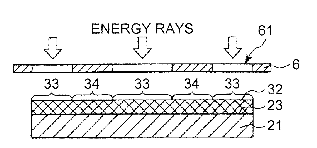
[0010]In the bonding method of the invention, the condition is preferably set by adjusting an amount of energy applied to the bonding film. Thus, the bonding strength of the bonded body can be easily adjusted. In the bonding method of the invention, the energy is preferably applied by at least one out of irradiating the bonding film with an energy ray, heating the bonding film, and applying a pressure on the bonding film so as to set the condition. This enables a surface of the bonding film to be efficiently activated so as to easily control the bonding strength of the bonding film. Additionally, since a molecular structure of the bonding film is not cleaved more than necessary, degrading a characteristic of the bonding film can be avoided.
[0011]In the bonding method of the invention, the energy ray is preferably an ultraviolet ray having a wavelength from 126 nm to 300 nm. The ultraviolet ray within the range allows an amount of applied energy to be optimized. Therefore, the molecular bond serving as a skeleton of the bonding film can be prevented from being destroyed more than necessary, and a molecular bond existing from the bonding film to around the surface can be selectively cleaved. Accordingly, characteristics (a mechanical characteristic, a chemical characteristic, and the like) of the bonding film can be prevented from being degraded, and adhesiveness of the bonding film can be surely developed, thereby allowing controlling the adhesiveness of the bonding film more easily.
[0012]In the bonding method of the invention, the energy is preferably applied in an ambient atmosphere. Accordingly, activation of the surface of the bonding film is performed more smoothly, whereby easily controlling the bonding strength of the bonding film. Further, without any trouble and cost for controlling an atmosphere, the application of energy can be more easily performed.
[0013]In the bonding method of the invention, in a plan view, the energy is preferably applied to the bonding film positioned at a first region and the bonding film positioned at a second region that is different from the first region under a different condition so that the bonding film positioned at the first region and the second region have different bonding strength. Accordingly, since the bonding film positioned at the first region and the bonding film positioned at the second region have different bonding strength, the bonding strength of the bonding film as a whole can be easily adjusted.

Problems solved by technology

However, the adhesive has the following problems: low in bonding strength, so that hard to adjust the bonding strength; low in dimensional accuracy; and it takes a long time to bond due to a long hardening time.
Therefore, costs and troubles due to using the primer result in increasing the costs and the complexity of the bonding process.
As a result, it is difficult to obtain desired bonding strength.

Method used


Image

  • Bonding method and bonded body
  • Bonding method and bonded body
  • Bonding method and bonded body

Examples


first embodiment

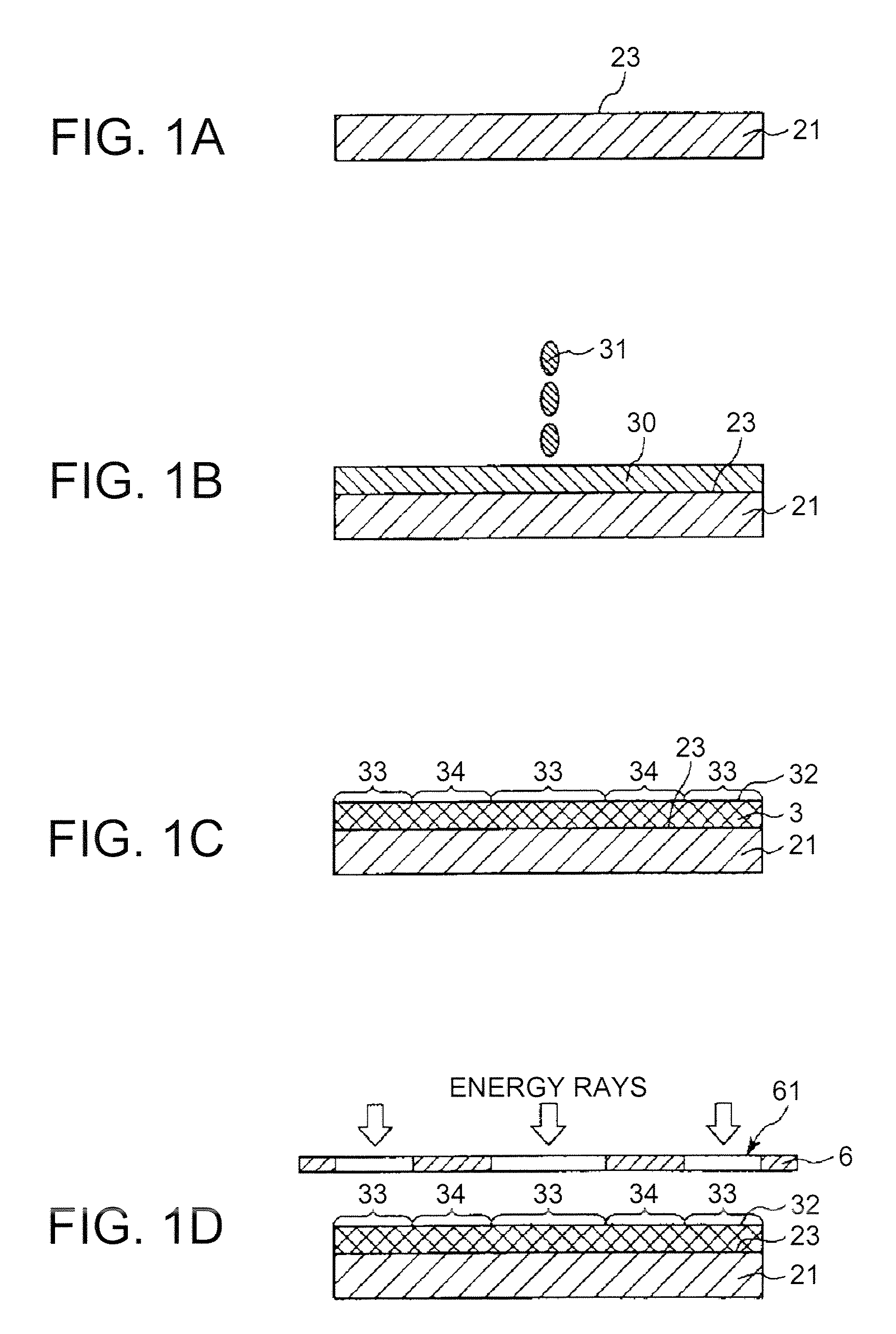
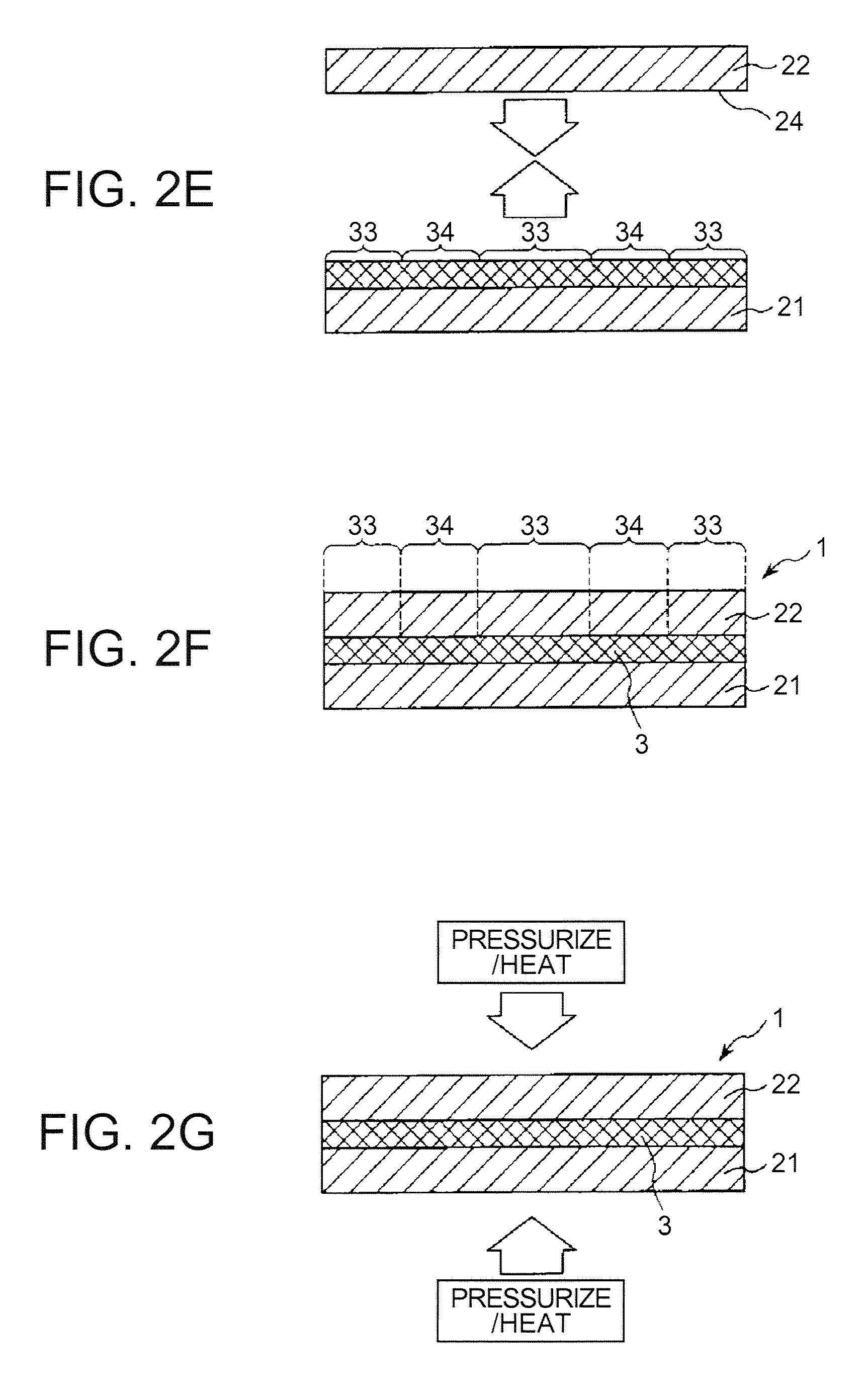
[0041]FIGS. 1A, 1B, 1C, 1D, 2E, 2F, and 2G are diagrams (vertical sectional diagrams) for explaining the first embodiment exemplifying the bonding method of the invention. Note that the top side of FIGS. 1A to 2G is referred to as “up” and the bottom side thereof is referred to as “down” in the following descriptions. In the bonding method of the present embodiment, the bonding film 3 is selectively formed on the first substrate 21 without being formed on the second substrate 22. Then, the first substrate 21 and the second substrate 22 are bonded together with the bonding film 3 interposed therebetween.

[0042]At a step 1, first, the first substrate 21 and the second substrate 22 are prepared. In FIG. 1A, the second substrate 22 is omitted. A constituent material of the first substrate 21 and the second substrate 22 is not particularly limited. Examples of the material include polyolefins such as polyethylene, polypropylene, ethylene-propylene copolymer, ethylene-acrylic acid ester co...

second embodiment

[0128]Next, a second embodiment of the bonding method according to the invention will be described. FIGS. 4A, 4B, 5C, 5D, and 5E are diagrams (vertical sectional diagrams) for explaining the second embodiment exemplifying the bonding method of the invention. Note that the top side of FIGS. 4A to 5E is referred to as “up” and the bottom side thereof is referred to as “down” in the following descriptions. The second embodiment of the bonding method will be described below. In the description, differences from the first embodiment of the bonding method will be mainly explained, and the same contents are omitted.

[0129]In the bonding method according to the present embodiment, the bonding film 3 is not only formed on the bond surface (the main surface) 23, but also formed on the bond surface (the main surface) 24 of the second structure 22 as well. Then, energy is applied to areas positioned at the first and the second regions 33 and 34 of the bonding film 3 included in the respective su...


PUM

PropertyMeasurementUnit
wavelengthaaaaaaaaaa
thicknessaaaaaaaaaa
thicknessaaaaaaaaaa

Abstract

A bonding method includes: preparing a first substrate and a second substrate; forming a liquid coating film by applying a liquid material including silicone to at least one of the first substrate and the second substrate; drying the liquid coating film so as to obtain a bonding film; and developing adhesiveness around a surface of the bonding film by applying energy to the bonding film so as to obtain a bonded body obtained by bonding the first substrate and the second substrate each other with the bonding film interposed between the first substrate and the second substrate. In the device, bonding strength of the bonding film is adjusted by appropriately setting a condition for applying the energy.

Description

[0001]The entire disclosure of Japanese Patent Application No. 2008-145877, filed Jun. 3, 2008 is expressly incorporated by reference herein.BACKGROUND[0002]1. Technical Field[0003]The present invention relates to a bonding method and a bonded body.[0004]2. Related Art[0005]When two members (substrates) are bonded (glued) each other, conventionally, methods using adhesives such as an epoxy adhesive, an urethane adhesive, and a silicone adhesive are often employed. The adhesives can exhibit adhesiveness regardless of the materials of the members. Therefore, members made of various materials can be bonded each other in different combinations. For example, a droplet discharge head (an inkjet recording head) included in an inkjet printer is composed by bonding members made of different materials such as resin material, metal material, and silicon material with an adhesive (JP-A-5-155017 is an example of related art).[0006]When the members are bonded with an adhesive, a liquid adhesive o...

Claims


Application Information

Patent Timeline
Patent Type & Authority Applications(United States)
IPC IPC(8): B32B27/04B32B37/12
CPCB32B37/00B32B2457/10B32B2310/0806
Inventor GOMI, KAZUHIRO
Owner SEIKO EPSON CORP
Learn More