For example, optical signals are progressively attenuated during propagation through a span, and amplified by an
optical amplifier (e.g., an
erbium doped
fiber amplifier (EDFA)) prior to being launched into the next span; however, signal degradation due to
noise and dispersion effects increases as the signal propagates through the
fiber.
Consequently,
noise and dispersion degradation are significant factors in limiting the maximum possible signal reach.
Chromatic dispersion in an
optical fiber presents a serious problem when using a
light source having a non-ideal spectrum, for example, a broad or multi-line
light source, or when high data rates are required (e.g., over 2 GB / s).
Consequently, chromatic dispersion is the
limiting factor for high
baud rate (e.g., greater than 10 Gbaud) communication systems for lengths exceeding a few kilometers.
In effect the
baud rate is reduced by a factor of two, leading to an improvement in dispersion tolerance by a factor of four; however, the multi-level modulation results in a
noise penalty of at least 5 dB compared to a non-return-to-zero (NRZ) signal at twice the baud rate.
At rates greater than 10 Gbaud, the MLSE
equalizer alone is insufficient to compensate for chromatic dispersion.
Other techniques such as a chirped pulse technique described in U.S. Pat. No. 4,979,234 titled “Saturated
Semiconductor Laser Amplifier for Compensation of Optical
Fibre Dispersion,” for managing chromatic dispersion in optical systems are known; however, these techniques also do not scale well with increasing baud rate.
For example, application of the chirped pulse technique can achieve a doubling of the dispersion tolerance so that the dispersion tolerance for a 40 Gbps signal improves from about 3.6 km to about 7.2 km; however, this improvement is an insignificant change for longer reach communication systems.
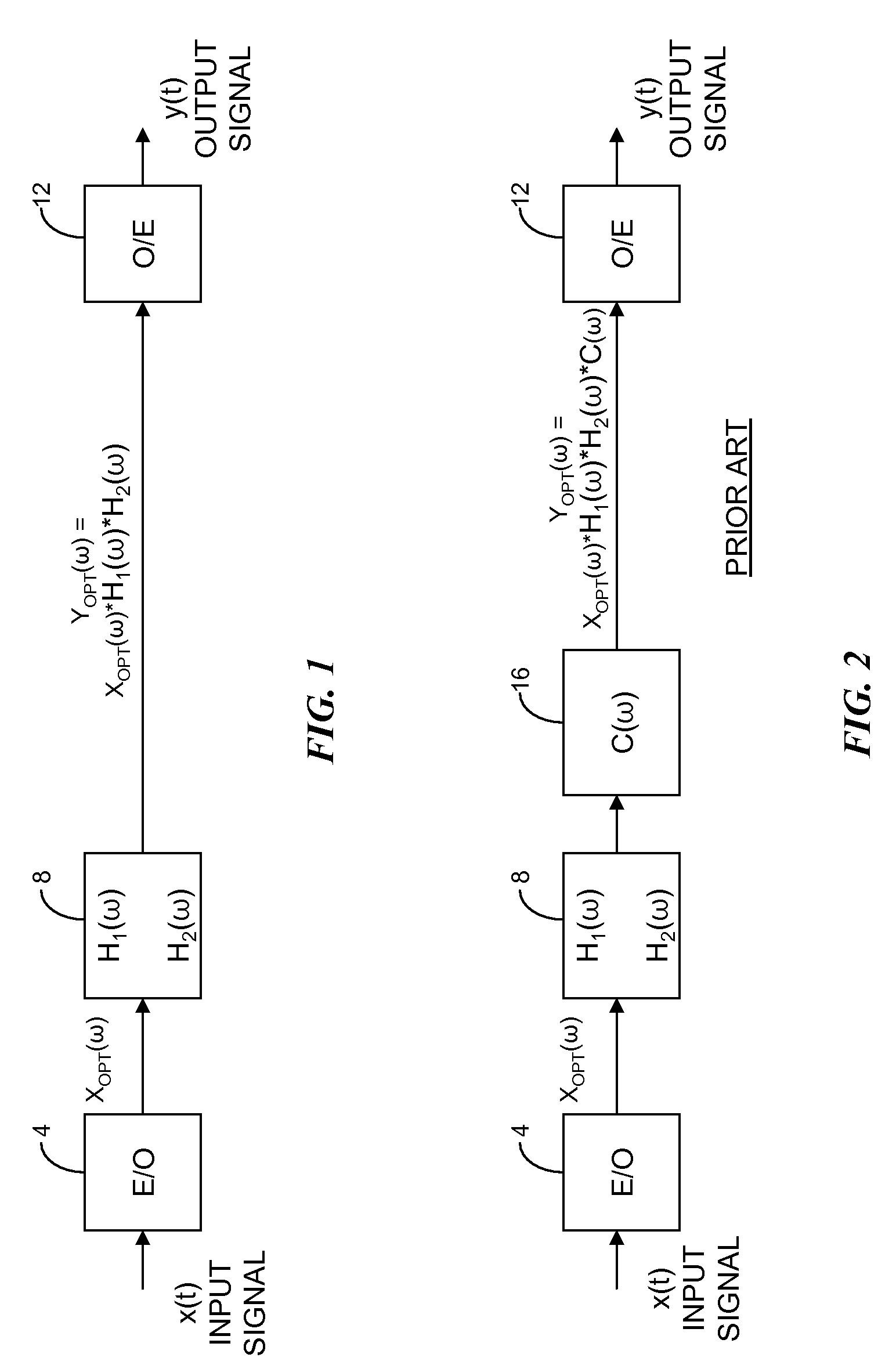
The compensation function C(ω)) is a dispersive function that is selected to optimize performance of the link for chromatic dispersion but in general does not address degradation due to polarization mode dispersion introduced by the link.
Limitations of optical components and the time-varying amount of compensation required make this objective difficult to achieve.
Additionally, the compensators represent an additional cost and introduce significant optical losses.
These losses are offset by means of additional optical
gain which introduces more
optical noise.
The additional (or higher-performance) optical amplifiers required to provide this increased
gain further increase the total cost of the
communications system.
In addition, the presence of compensators for chromatic dispersion and high performance amplifiers distributed along the length of the link provides a significant technical barrier to
system evolution.
In a complementary manner, an optical
communications system can utilize a chromatic dispersion function in the electrical domain at the
receiver; however, this represents a limited capability for direct detection modulation systems as the compensation function is nonlinear and the phase information is not available.
To compensate for polarization mode dispersion at the transmitter, access to both polarization components is required, resulting in a significant additional cost to the communications
system.
The transmitter requires knowledge of the polarization states and differential
delay; however, this information is only available at the
receiver.
Although the receiver can send this information to the transmitter, the latency in reporting the information to the transmitter can make compensation of polarization mode dispersion at the transmitter impractical.
More specifically, by the time the information is received at the transmitter, the polarization mode dispersion imparted by the optical link may have changed so that the information is no longer useful.

