Vertically Integrated Greenhouse

a vertical greenhouse and greenhouse technology, applied in the field of vertical greenhouses, can solve the problems of increasing traffic congestion, air pollution and carbon emissions, reducing yields, and increasing environmental pressure, and reducing solar heat gain. , the effect of reducing the effect of urban heat island

Active Publication Date: 2009-12-17
NEW YORK SUN WORKS
View PDF7 Cites 99 Cited by
  • Summary
  • Abstract
  • Description
  • Claims
  • Application Information

AI Technical Summary

Benefits of technology

[0045]Vertical spacing between trays on the cable can also be varied. Rows can be more tightly spaced in winter, when the sun is lower, resulting in steady yields year-round. In winter, when the greenhouse is installed in a double glazed façade, the vertically integrated greenhouse is an effective solar capture device, warming and insulating the glazed façade of the b

Problems solved by technology

Three major trends will strain the global food system over the next half-century, and place significant additional pressure on the environment.
Second, more than two-thirds of these people are expected to be urban dwellers.
Fresh produce travels an average of 2500 km to reach U.S. cities, ad

Method used


Image

  • Vertically Integrated Greenhouse
  • Vertically Integrated Greenhouse
  • Vertically Integrated Greenhouse

Examples


first embodiment

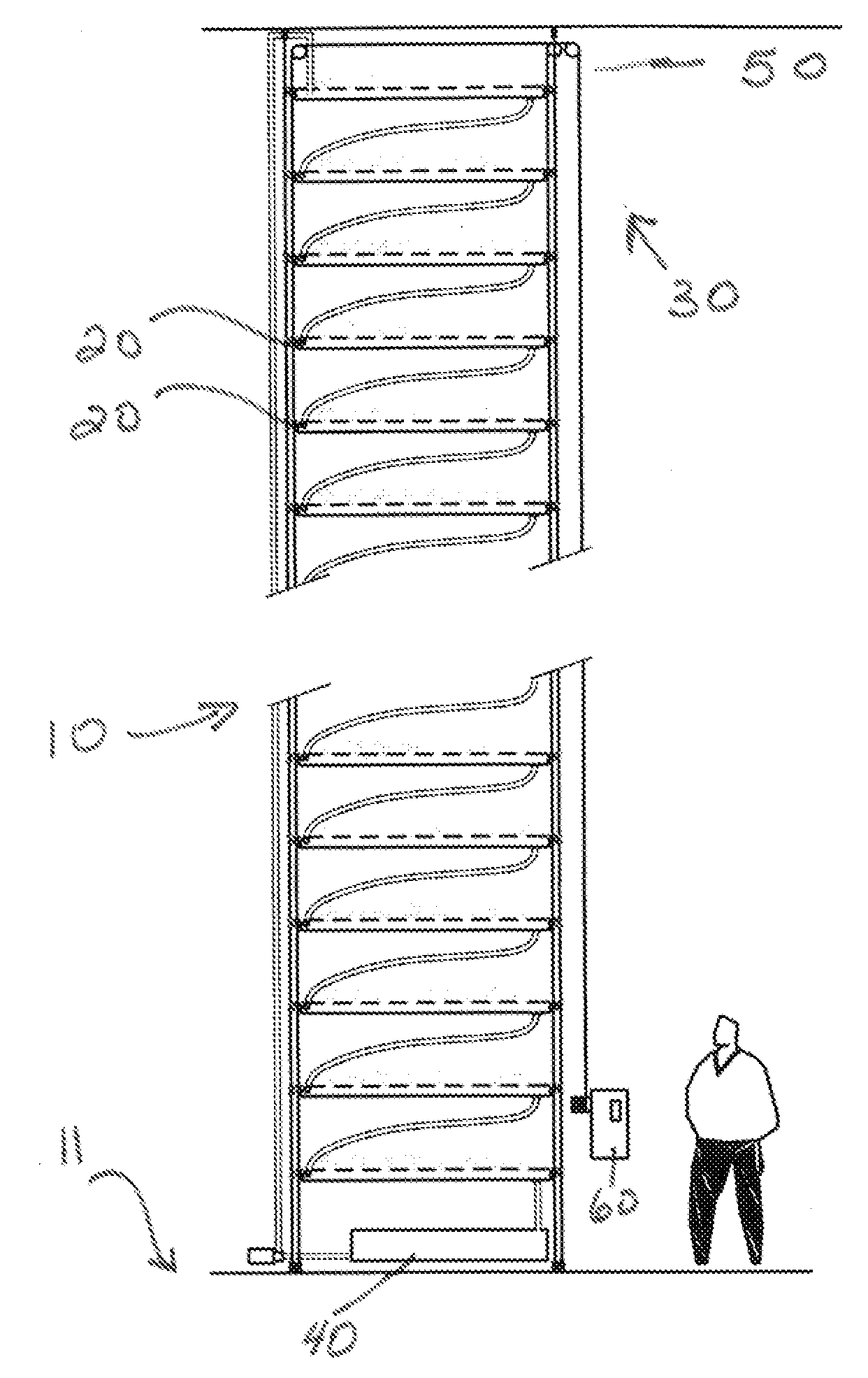
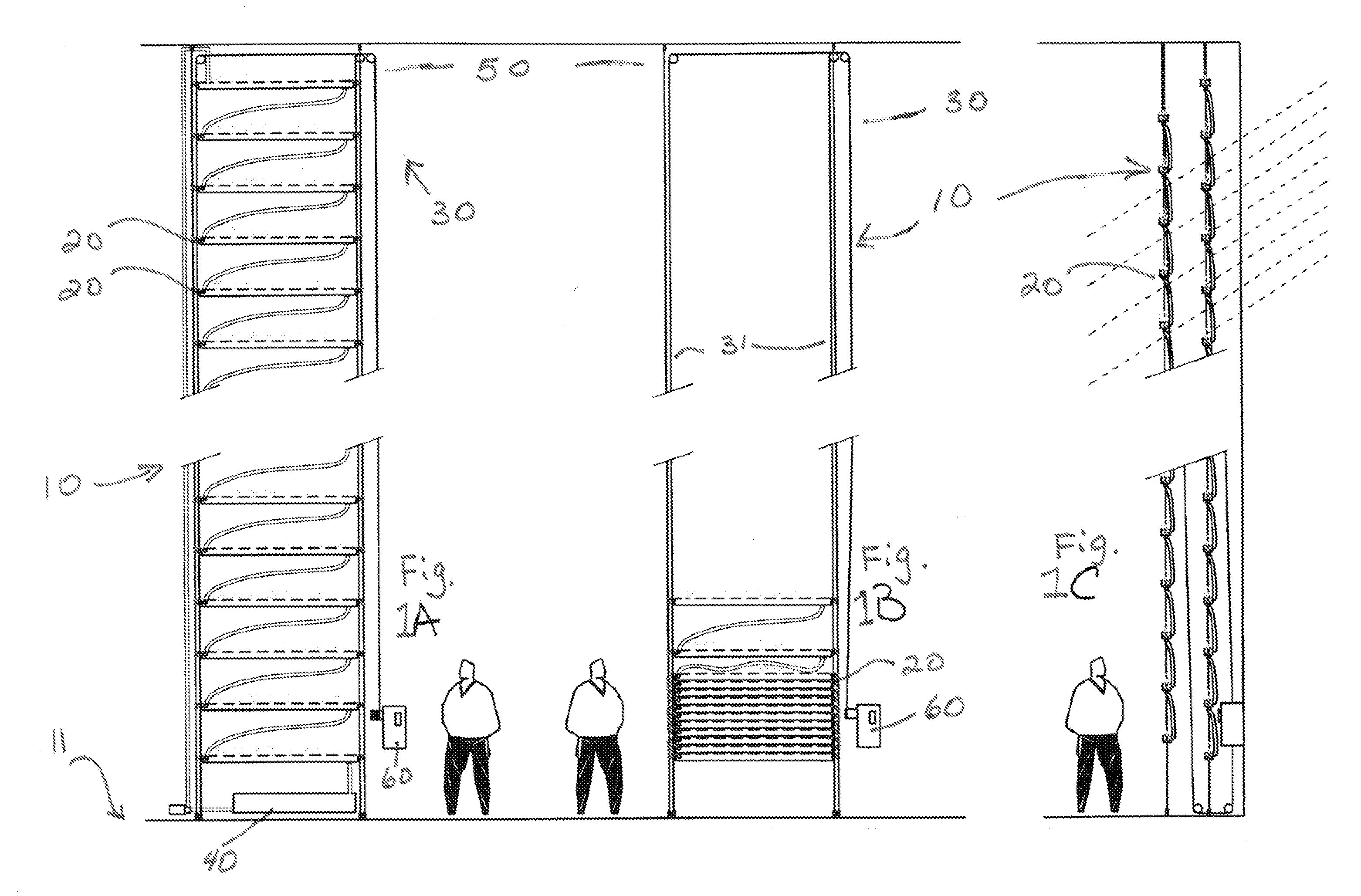
[0062]In the VIG-system (FIGS. 3-10, discussed below), termed the “collapsible” or “shade system” embodiment, plant cable lift systems are used to raise and lower trays. In such an embodiment, the trays are fastened to drive train guide wires by way of fasteners. To mount the trays to the drive train, L-shaped brackets may be attached to the top of the tray at both ends, and these brackets may have clevis ends bolted into them. The clevis ends can be opened with a latch and the trays removed from the guide wires. The wires may have set screw collars placed at measured distances that hold up the trays. The screw collars have a larger outside diameter than the inside diameter of the clevis openings to ensure the trays do not slip down the wires. The specific kind of fastener is not critical, and the use of other kinds of fasteners to secure the trays to the tray suspension system is within the scope of the present invention.

[0063]In this embodiment of the invention, there are two sets...

second embodiment

[0065]In the invention (FIGS. 11-16), termed the “conveyer” embodiment, a hollow pin chain drive serves to circulate the trays through the greenhouse. In this embodiment, L-shaped gutter brackets have a pin bolted through them. The pin is attached through a hollow pin chain link on the chain which drives the system. The link and pin assembly has springs to maintain tension so that the trays can be removed but will not slip out of the chain drive. The trays can be removed by unbolting the hanging pin at either the chain or gutter bracket points.

[0066]The chain drive is mounted on cogs which are attached to arms (or cog hangers) that hold up the entire system. The chain drive can be embedded in a baffled vertical gutter on the drain or down slope side. Baffling in the return gutter can be used for water containment and channeling to avoid exposing the chain to water flows. The hanging pin is shaped so as to permit the trays to maneuver as they travel in the conveyor system. The hangin...


PUM


Abstract

A vertically-integrated greenhouse for growing plants in suspended trays. The design is particularly well-suited for installation in a double-skin façade of a building, or in an interior atrium, lobby, or similar structure. In addition to producing food, plants can reduce building maintenance costs by providing shade, air treatment, and evaporative cooling to building occupants. The vertically-integrated greenhouse involves the use of a dynamic movable array of plant trays as a mechanical shading device. The spacings and arrangements of the trays in the tray suspension system can be adjusted on both a diurnal basis and a seasonal basis to maximize plant light capture and building shading, thereby maximizing crop yield and building energy savings, or for esthetic considerations.

Description

CROSS REFERENCE TO RELATED APPLICATION[0001]This application claims the priority benefit of U.S. provisional patent application Ser. No. 61 / 073,303, filed on Jun. 17, 2008, the contents of which are incorporated by reference herein in their entirety.FIELD OF THE INVENTION[0002]The present invention relates to structural systems for growing plants in urban settings. In particular, the invention is directed to a vertical greenhouse which is affixed to a façade of a multi-story urban building, or to the wall of a multi-story atrium or concourse.BACKGROUND OF THE INVENTION[0003]Increasing urban growth and global construction surges have underscored the importance of efficiency in the built environment. In the United States, buildings account for over a third of total energy use, two-thirds of electricity consumption, one-twelfth of the country's water consumption, and two-fifths of carbon dioxide emissions.[0004]Agriculture has an equally significant impact on our world. Modern agricult...

Claims


Application Information

Patent Timeline
IPC IPC(8): A01G9/02A01G31/06
CPCA01G31/06A01G9/14A01G9/1423Y02A40/25Y02P60/21
Inventor ADAMS, ZAKERY WARDCAPLOW, JR., THEODORE
Owner NEW YORK SUN WORKS
Why Eureka
Try Eureka