Heat transfer assembly and methods therefor

a technology of heat transfer and assembly, which is applied in the direction of heat transfer modification, indirect heat exchangers, lighting and heating apparatus, etc., can solve the problems of heat removal, excess processing stress and overall assembly complexity and cost, and limit the design of thermal transfer devices to materials with similar tec, etc., to achieve good conductive exchange, high convective exchange, and high thermal stress tolerance

Inactive Publication Date: 2009-12-17
THERMAL CENTRIC CORP
View PDF4 Cites 58 Cited by
  • Summary
  • Abstract
  • Description
  • Claims
  • Application Information

AI Technical Summary

Benefits of technology

[0019]Embodiments of the present invention generally relate to thermal exchangers. Certain embodiments relate to the use of thermally conductive open cell graphitic foam (GF), GF composites, and

Problems solved by technology

However, permanent or semi permanent bonding inherently causes local stresses at the interface, which are dictated mainly by the divergence in the effective thermal expansion coefficient (TEC) between the parts, thereby effectively limiting the design of thermal transfer devices to materials with similar TEC.
Such physical bonding also results in excess processing stresses and overall assembly complexity and cost.
With higher density per area per die of integrated circuits (ICs), and more die per area on assembly boards, heat removal becomes an engineering challenge.
In heat transfer devices where size, weight, and efficiency are critical parameters, the surface area per volume, the material density, and the thermodynamic properties of the material become increasingly important factors, limiting fabricated (machined or manufactured) fins and extended surfaces due to the strict limitations on the amount of heat managed.
The thermal conductivity of typical heat transfer materials also limits the amount of heat managed within a given volume.
This permanent or semi permanent bond inherently causes local stresses at the interface, which are dictated mainly by the divergence in the effective thermal expansion coefficient (TEC) between the parts thereby effectively limiting the design of

Method used


Image

  • Heat transfer assembly and methods therefor
  • Heat transfer assembly and methods therefor
  • Heat transfer assembly and methods therefor

Examples


example i

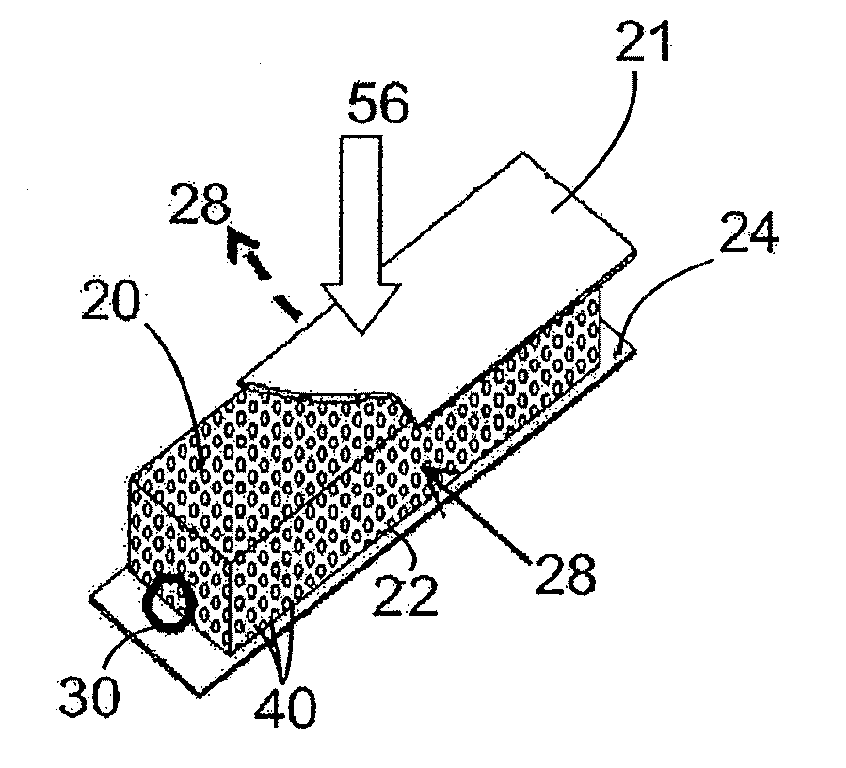
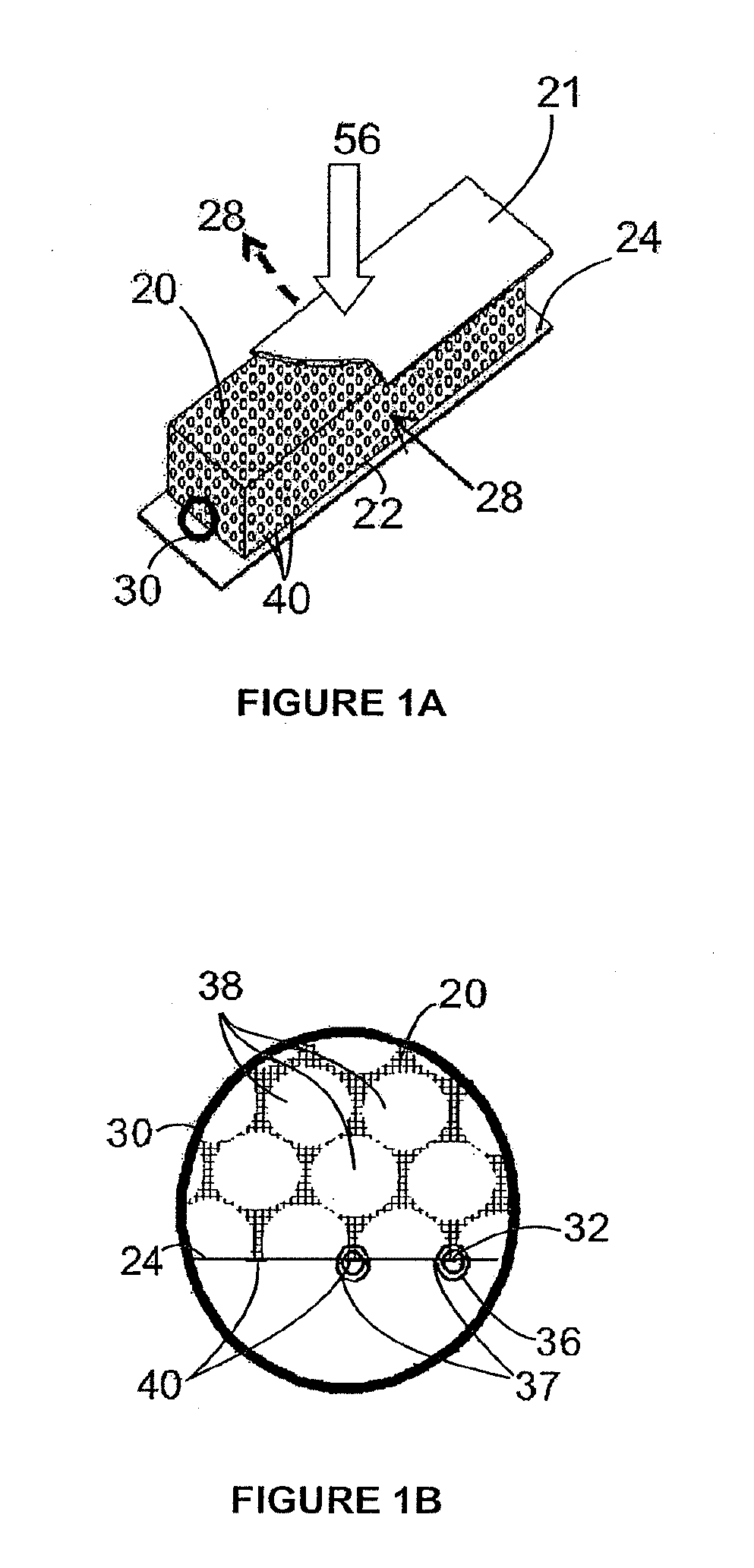
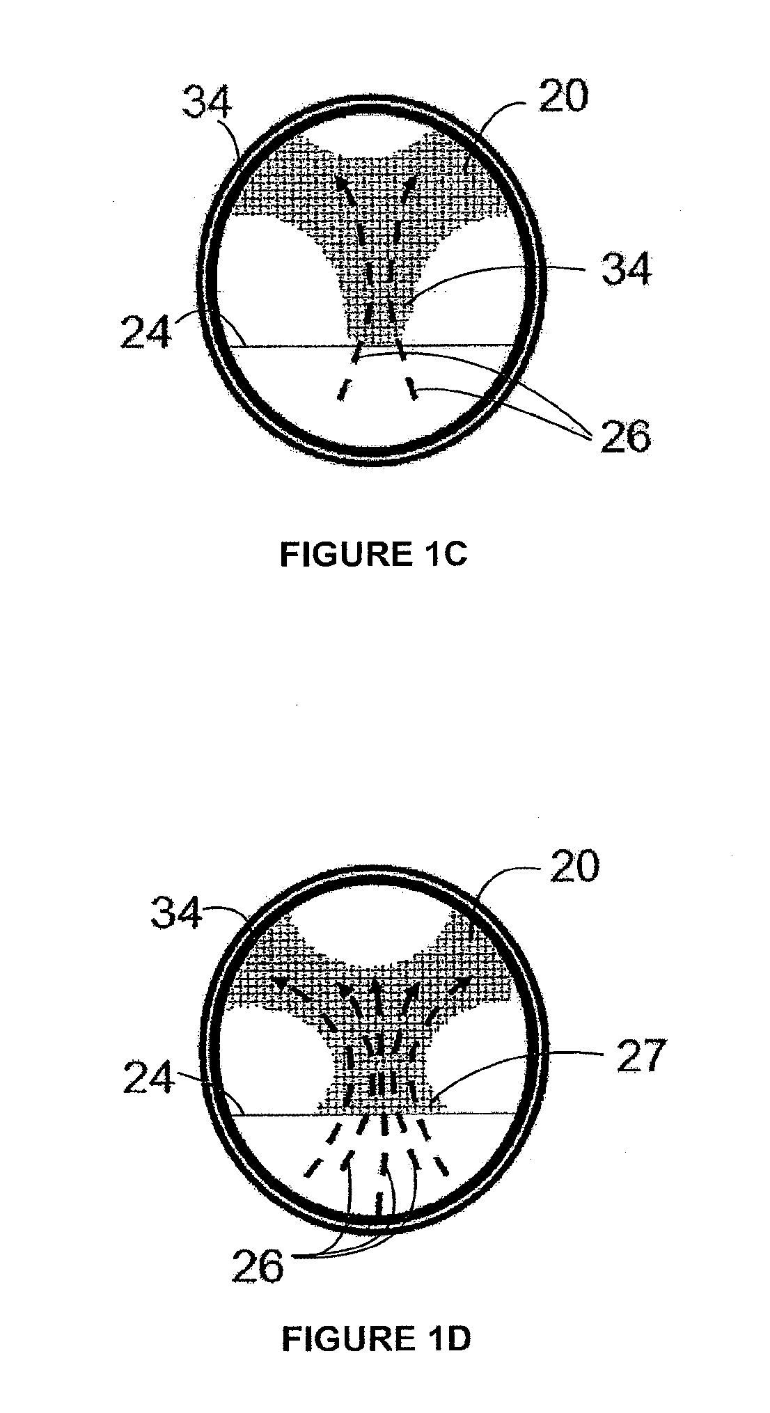
[0091]A first embodiment will be described by reference to the drawings. In this embodiment the heat transfer assembly as referenced in FIG. 1 comprises at lease one segmented, formed or simple block of graphite based foam 20 in thermal contact with the heat exchange surface 24 through direct compression of GF material 20 to said surface 24 creating an acceptable thermal junction 22 with a low and mostly temperature independent thermal contact impedance. During normal operations the heat in block is dissipated through convection by directing a fluid coolant 56 through the block 20 relative to the heat flow 58 at the surface, as seen in FIG. 1c.

[0092]FIG. 2a illustrates an embodiment seen as a preassembled unit 23, having an element bottom contact surface 21 which can be modified by the addition of a volumetric recess for conformal connection to the heat exchange surface 24 topography. Here the foam element is operably secured to enable compression force 63 by means of an exemplary ...

example ii

[0093]A second embodiment of the invention will be described by reference to the drawings, and the structure of a thermal heat exchange assembly according to this embodiment will be described in terms of manufacturing steps.

[0094]FIG. 3 shows an embodiment which may include several GF elements 20 being coplanarly located in one or more axial directions sequentially forming a multielement layer 62. Said element layer 62 can be connected by separate 64 or common mechanical attachment mechanisms 66, wherein the GF material layer 62 is sandwiched between the heat exchange surface 24 and the attachment mechanism 60. Any or all of the elements, surfaces and mechanisms may 67 or may not 65 have a volumetric recess for conformal connection of the parts through geometrical or alignment topography.

[0095]With reference to FIG. 3, a heat exchanger GF element assembly may have varying densities of GF 20 in order to match varying heat dissipation requirements on the surface of the module. Additio...

example iii

[0096]Further embodiments of the present invention are illustrated in FIGS. 4 and 5 which explain a third embodiment of the invention is described as a stacked multilayer heat exchange assembly formed by alternating foam element layers and barrier layers which are effectively sandwiched between the heat exchange surface and the attachment mechanism.

[0097]This embodiment can exhibit several possible variations in relative size and geometry. The basic heat exchange mechanism of this element is identical with that of the first embodiment. This plurality of array elements must be stacked as to ensure proper compression on all layers, therefore the layout can contain alignment marks or features to simplify assembly and integration of the same.

[0098]FIG. 4a illustrates an exemplary stack 70 anchored to a base 72 whereby all the barrier layers 73 are also exchange surfaces 74, composed of flat tubes 75, only serve as a separating boundary for each element layer 20 and a separate mechanical...


PUM

PropertyMeasurementUnit
Lengthaaaaaaaaaa
Thermal conductivityaaaaaaaaaa

Abstract

Embodiments in accordance with the present invention relate to heat exchangers, and more specifically to graphitic foam (GF) heat exchanger assemblies developed for a plurality of thermal management applications including the management of heat from electronic components, primary engine cooling and energy recovery. According to certain embodiments, these assemblies are designed using a pressure normal to the GF exchange element to ensure thermal contact without the use of bonding materials or methods. The bondless assembly is designed to be resistant to high thermal stresses and large thermal expansion coefficient differences thereby achieving and maintaining the highest possible thermal performance.

Description

CROSS-REFERENCE TO RELATED APPLICATIONS[0001]The instant nonprovisional patent application claims priority to the following U.S. Provisional Patent Applications, each of which is incorporated by reference in its entirety herein for all purposes: U.S. Provisional Patent Application No. 61 / 052,134, filed May 9, 2008; U.S. Provisional Patent Application No. 61 / 052,143, filed May 9, 2008; U.S. Provisional Patent Application No. 61 / 083,060, filed Jul. 23, 2008; U.S. Provisional Patent Application No. 61 / 084,405, filed Jul. 29, 2008; U.S. Provisional Patent Application No. 61 / 086,758, filed Aug. 6, 2008; and U.S. Provisional Patent Application No. 61 / 114,036, filed Nov. 12, 2008.BACKGROUND OF THE INVENTION[0002]Efficient thermal energy exchange is vital for today's microelectronic devices. As these devices continue to be reduced in size, power density and heat generation from these devices also increases. To manage this issue, heat transfer devices haven been utilized as attachment member...

Claims


Application Information

Patent Timeline
IPC IPC(8): F28F7/00F28F13/00F28D15/00B23P19/04
CPCF28F13/003F28F21/02G06F1/20H01L23/3733H01L23/427Y10T29/53H01L2924/3011F28F2013/006H01L2924/0002H01L23/467H01L2924/00
Inventor THOMPSON, BRIAN E.YU, QIJUNBARIAULT, JOSEPH DANIELSTRAATMAN, ANTHONY G.REDMAN, PAUL
Owner THERMAL CENTRIC CORP
Why Eureka
Try Eureka