Systems and methods for electrochemical power generation

a technology of electrochemical power generation and systems, applied in the direction of electrochemical generators, aqueous electrolyte fuel cells, cell components, etc., can solve the problems of toxic to fish and aquatic insects, adverse environmental effects, and general view of undesirable impurities

Inactive Publication Date: 2009-12-17
DANZIGER ROBERT
View PDF5 Cites 17 Cited by
  • Summary
  • Abstract
  • Description
  • Claims
  • Application Information

AI Technical Summary

Benefits of technology

[0009]Systems, compositions and methods are provided for electrochemical power generation, wherein the non-carbon constituents of a fossil fuel are oxidized to obtain energy at a temperature below the oxidation temperature of carbon. Additional aspects include systems and methods for remediating acid mine drainage (AMD), where, in some instances, the systems are configured to raise the pH of AMD. In certain embodiments, the non-carbon constituents of the fossil fuel are regenerated using electricity (either chemically or biologically). In certain embodiments, the non-carbon constituent of the fossil fuel oxidized by the electrochemical power generation system is a metal-sulfide. Thus, in some cases, the electrochemical power generation system is a metal-sulfide electrochemical power generation system. In some cases, the non-carbon constituents of fossil fuels are pyritic sulfur and iron constituents. In certain emb

Problems solved by technology

Coal is our most abundant fossil fuel; however, there are a number of adverse environmental effects of coal mining and burning.
These impurities are generally viewed as undesirable contaminants that need to be scrubbed from the desired hydrocarbons.
Even in moderate concentrations, AMD is toxic to fish and aquatic insects that fish eat.
AMD is characterized by high acidity, high metal concentrations such as iron, high su

Method used


Image

  • Systems and methods for electrochemical power generation
  • Systems and methods for electrochemical power generation
  • Systems and methods for electrochemical power generation

Examples


example 1

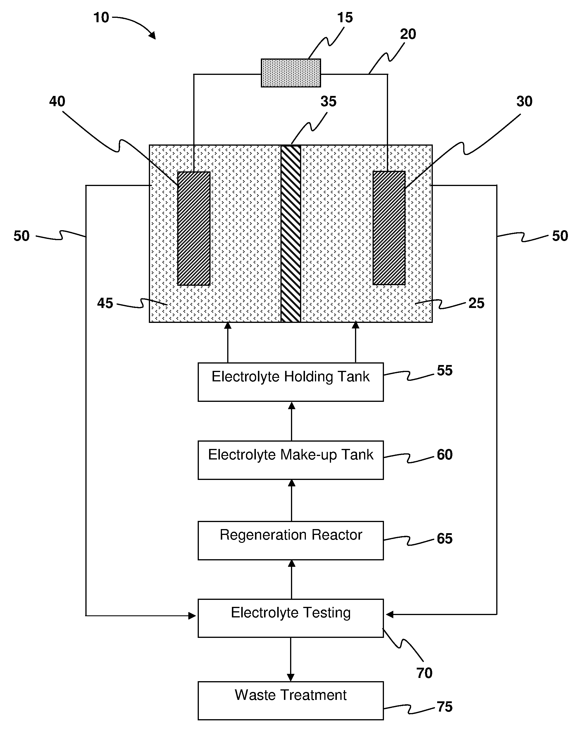
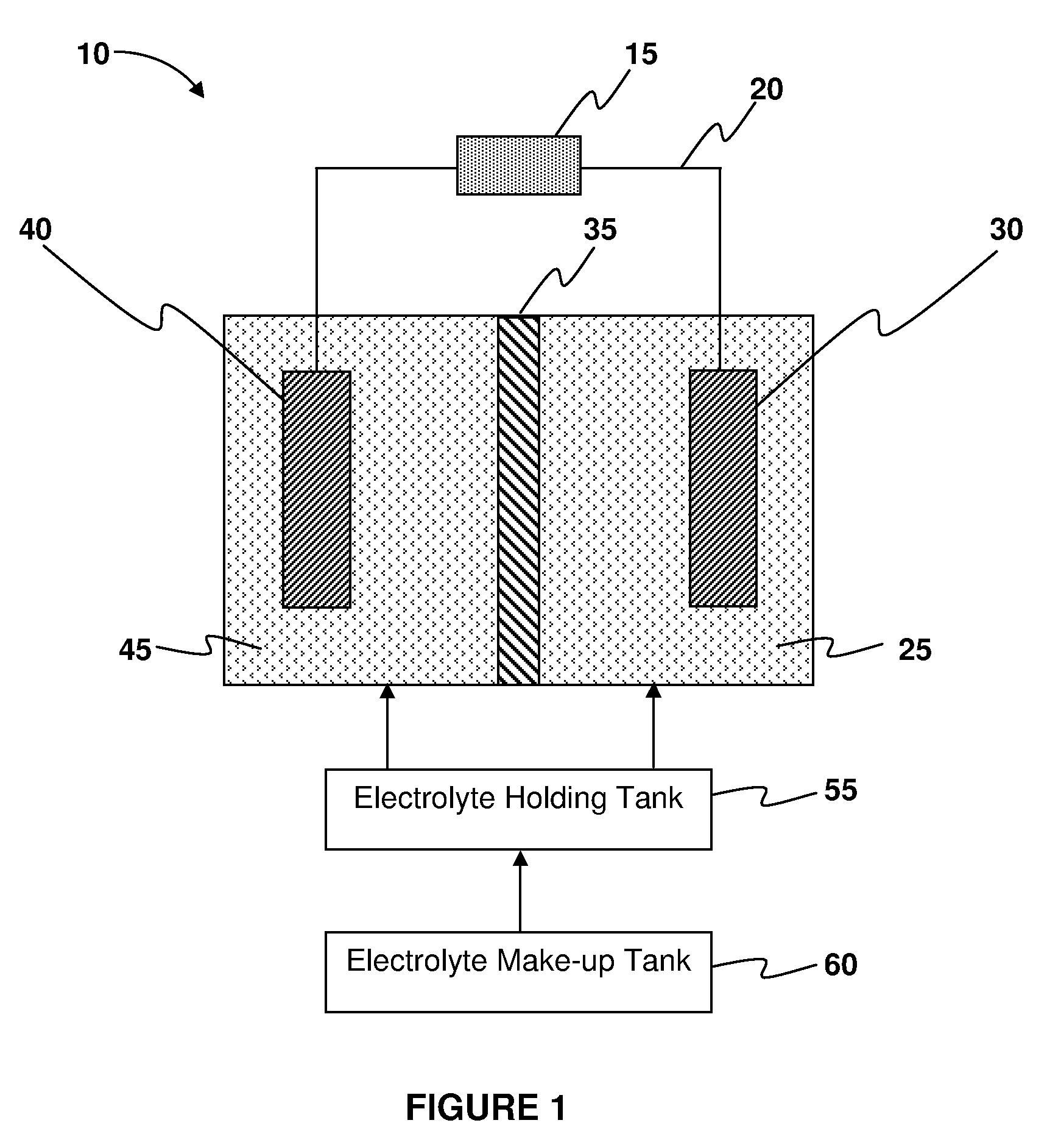
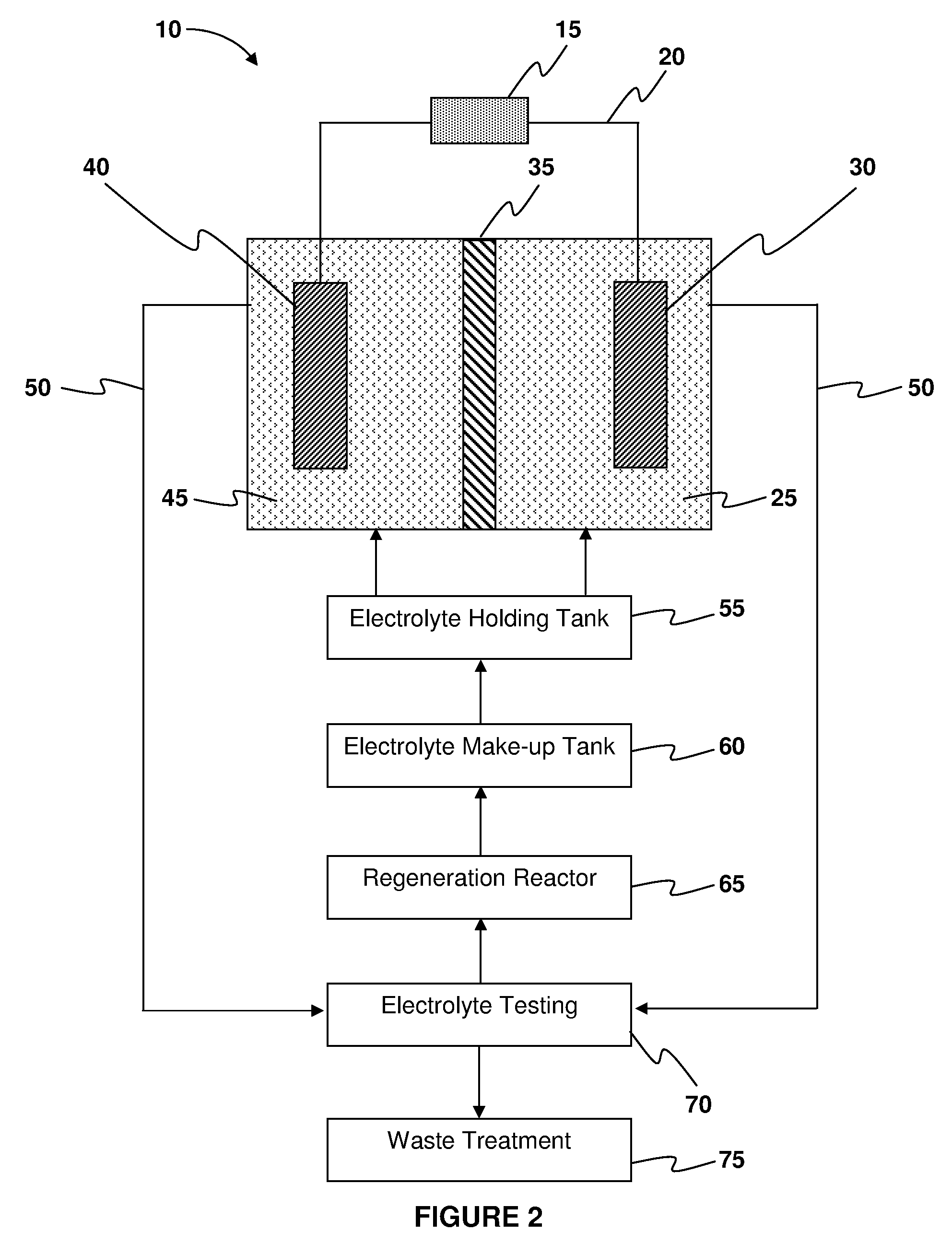
[0105]A continuous flow electrochemical power generation system was tested using acid mine drainage (AMD) as the aqueous electrolyte medium and reticulated vitreous carbon (RVC)— zinc electrode pairs. At time=zero, started pumping AMD into 1.5 liters of tap water. Three RVC-zinc electrode pairs in switch holders were used. Resistance was set at 100 ohms. tzero V was 0.03V. Pump flow rate was 350 L / h. Sparging was with three tubes, and the initial pH of the AMD was 2.5. The voltage of the fuel cell is shown in Table 1 below.

TABLE 1Time (minutes)VoltsNotes100.84201.24301.27401.27501.271701.222301.35(1.34 mW / cm2)Sparging wasincreased.1,0800.87

example 2

[0106]In this example, a static system was used (i.e., no flow-through). One 12 volt lead-acid battery was filled with AMD and tested for power density. The electrode dimensions were as follows: 3 inches wide, 5 inches deep, 5 inches high. The electrode had 15 square inches of face area. Resistance values were varied using a millennium box, and voltages measured. At tzero V=0.915 V. With no load and after the battery was filled with AMD, V=7.0 within minutes. With a decade box and no load, V=0.49 V. The results are shown in Table 2 below.

TABLE 2resistance(ohms)voltsampswattsW / cm2mW / cm200.811.31.3001.6900.017517.4621.70.8501.4450.014914.9331.90.6331.2030.012412.3442.10.5251.1030.011411.3952.40.4801.1520.011911.9062.50.4171.0420.010810.7672.70.3861.0410.010810.7682.80.3500.9800.010110.1392.90.3220.9340.00979.66103.10.3100.9610.00999.93113.20.2910.9310.00969.62123.30.2750.9080.00949.38133.40.2620.8890.00929.19143.50.2500.8750.00909.04153.60.2400.8640.00898.93163.60.2250.8100.00848.3717...

example 3

[0107]Examples were performed using a coal / iron anode and an air cathode. Measurements were taken using a standard decade box and multimeter configuration. The batteries used were Wee-K Enterprises CMAB5A, which include a rubber / plastic housing with five slots, two air cathodes 4″×4″ per slot, for a total of 10 air cathodes. The wiring harness was a simple two-wire bus design. The two air cathodes per slot had a wire connecting the two sides, which was connected to the bus at its center. With respect to the anode, the use of pyrite in waste coal (iron and sulfur) as an anode was tested. This configuration significantly reduced the anode cost because the fuel was also the anode. One iron strip 5.5″ long by ¾″ wide was inserted in each of the five slots and wired to connect to the bus. Two ounces of Scrubgrass coal was placed in each slot. 500 mL simulated AMD type I was used as the electrolyte. Results are shown in Table 3, below.

TABLE 316:2216:45ohmsvoltswattsvoltswatts13.009.003.08...


PUM


Abstract

Electrochemical power generation systems in which the oxidizable reactant is non-carbon constituents of a fossil fuel are provided. The fossil fuel may be coal, which is contacted with an aqueous electrolyte medium used in the systems. The electrolyte may, in certain aspects, be acid mine drainage. Aspects of the invention include systems and methods for remediation of acid mine drainage, where the systems are configured to raise the pH of acid mine drainage. Aspects of the invention also include regenerating the electrolyte using an external electricity source and recirculating the electrolyte to the system.

Description

CROSS-REFERENCE TO RELATED APPLICATIONS[0001]Pursuant to 35 U.S.C. § 119 (e), this application claims priority to the filing date of U.S. Provisional Application Ser. No. 61 / 061,945 filed Jun. 16, 2008 and U.S. Provisional Application Ser. No. 61 / 090,160 filed Aug. 19, 2008; the disclosures of which applications are herein incorporated by reference.INTRODUCTION[0002]Coal is our most abundant fossil fuel; however, there are a number of adverse environmental effects of coal mining and burning. Burning coal causes the release of carbon dioxide, which is a greenhouse gas that contributes to climate change and global warming. In addition, the release of carbon dioxide into the atmosphere contributes to ocean acidification, which is the ongoing decrease in the pH of the Earth's oceans, caused by their uptake of anthropogenic carbon dioxide (i.e., carbon dioxide derived from human activities) from the atmosphere.[0003]In addition to hydrocarbons, coal contains significant amounts of organi...

Claims


Application Information

Patent Timeline
IPC IPC(8): H01M8/18H01M8/04
CPCH01M4/861H01M8/0245Y02E60/521H01M8/1004H01M8/1009H01M8/04261H01M8/04197Y02E60/50
Inventor LEVINE, R. PAULDANZIGER, ROBERT
Owner DANZIGER ROBERT
Why Eureka
Try Eureka