
Sample target having sample support surface whose face is treated, production method thereof, and mass spectrometer using the sample target

a technology of sample support surface and sample target, which is applied in the direction of particle separator tube details, instruments, separation processes, etc., can solve the problems of insufficient detection sensitivity and durability in practical use, difficult to analyze sample ions depending on related ions, and difficult to analyze sample ions, etc., to achieve efficient and more stable ionization of sample, suppress the oxidization of fine bumpy structure, and increase conductivity

Inactive Publication Date: 2009-12-24
JAPAN SCI & TECH CORP +1
View PDF4 Cites 22 Cited by
  • Summary
  • Abstract
  • Description
  • Claims
  • Application Information

AI Technical Summary

Benefits of technology

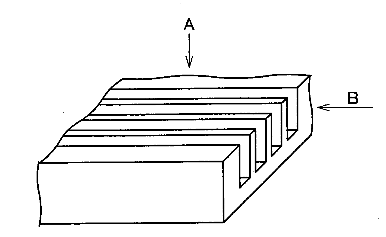
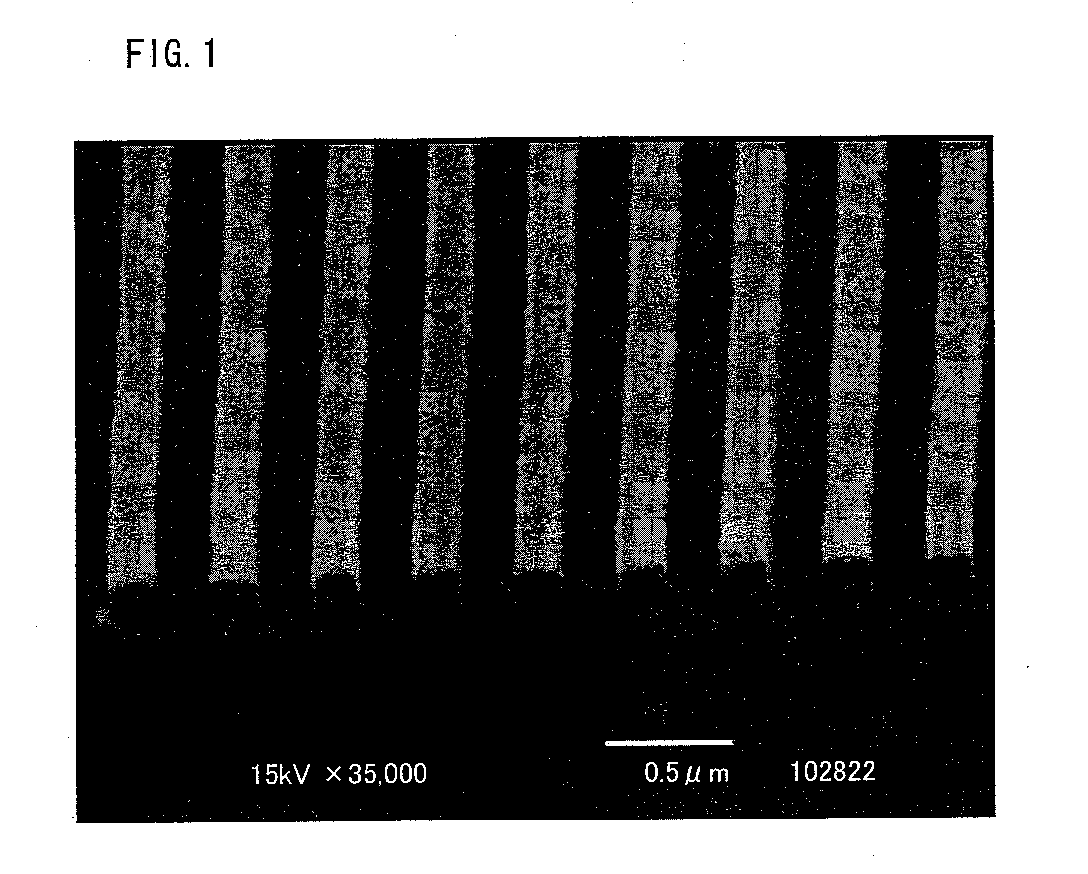
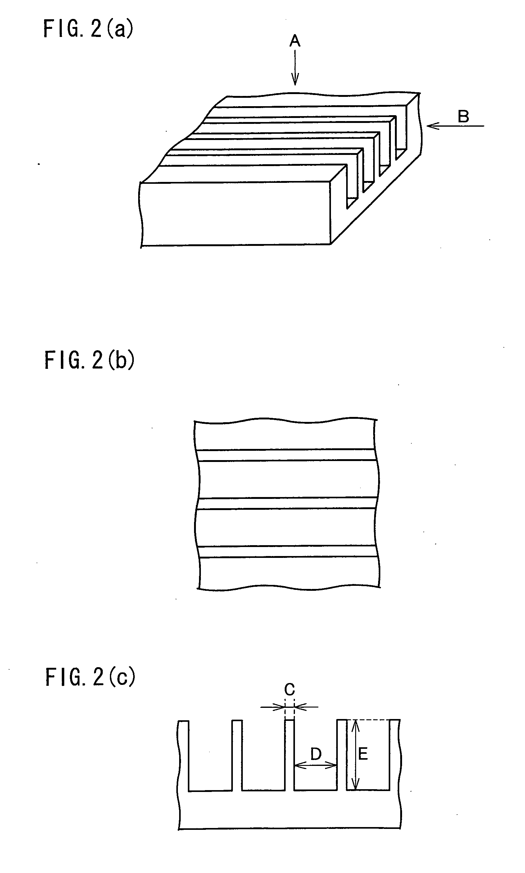
The present invention relates to a sample target for mass spectrometry that includes a surface with a finely bumpy structure. The bumpy structure is coated with metal to efficiently and stably ionize the sample. The sample target has a high reproducibility and stability for analyzing samples using laser irradiation. The concave portions on the surface of the sample support have a regular arrangement, and the interval and width of each concave portion are optimized for mass spectrometry. The sample target is produced by coating a substrate with metal and repeatedly disposing concave portions on the surface of the substrate. The mass spectrometer using this sample target performs accurate and reliable mass spectrometry.

Problems solved by technology

However, MALDI uses an organic compound matrix, so that it may be difficult to analyze sample ions depending on related ions derived from the matrix.
Specifically, in case where the organic compound matrix is used, there are observed matrix-related ions such as (i) matrix molecule ions, (ii) cluster ions caused by hydrogen bond of matrix molecules, (iii) fragment ions generated by decomposition of matrix molecules, so that it is often difficult to analyze the sample ions.
However, the method in which the matrix is fixed in the foregoing manner raises such a problem that detection sensitivity and durability are insufficient in practical use.
Further, the method also raises such a problem that it is impossible to avoid a noise caused by the fragment ions.
Note that, in the sample target, when the sample support surface having the finely bumpy structure is oxidized, the sample is less efficiently ionized.
However, in case where the sample support surface is chemically modified with an organic compound in order to avoid drop in the sample ionization efficiency which is caused by oxidization of the sample support surface, the oxidization is suppressed, but the sample is less efficiently ionized than the case where the sample support surface is not chemically modified.
In case where the intensity of the laser beam is raised in order to avoid drop in the ionization efficiency which is caused by the chemical modification, ions of the sample are likely to be decomposed, so that it is difficult to obtain accurate analysis results.
In case of avoiding this trouble, it is difficult to perform stable ionization.
However, the mass spectrometry based on DIOS in which the sample support surface has the irregularly bumpy structure in this manner raises such a problem that an analysis result obtained therefrom is likely to be less stable.
Therefore, it is difficult to form a similar bumpy structure with high reproducibility.
As a result, the sample ionization is less stable, so that an analysis result obtained therefrom is less stable.

Method used


Image

  • Sample target having sample support surface whose face is treated, production method thereof, and mass spectrometer using the sample target
  • Sample target having sample support surface whose face is treated, production method thereof, and mass spectrometer using the sample target
  • Sample target having sample support surface whose face is treated, production method thereof, and mass spectrometer using the sample target

Examples


example 1

[0149]In the present Example, Pt was deposited on a sample support surface of a DIOS sample target by adopting a sputtering technique so that Pt had the thickness of 20 nm, thereby producing a sample target. The sample target coated with Pt was used to perform mass spectrometry on the basis of laser desorption ionization. A procedure and results thereof are explained as follows.

[0150]Pt was deposited on a DIOS sample target (product of Mass Consortium (U.S.)) by TFL-1000 ion sputtering device (product of JEOL) so as to have the thickness of 20 nanometer. FIG. 8 illustrates a cross sectional view obtained by observing a cross section of a treated sample support surface of the DIOS sample target with a scanning electron microscope. As illustrated in FIG. 8, in the bumpy structure of the sample support surface of the DIOS sample target, the shape of the concave portion is not constant, and an interval of convex portions or concave portions adjacent to each other in the bumpy structure ...

example 2

[0160]In the present Example, Pt was deposited on a porous plastic Portex by adopting a sputtering technique so as to have the thickness of 20 nm, thereby producing a sample target. The sample target coated with Pt was used to perform mass spectrometry on the basis of laser desorption ionization. A procedure and results thereof are explained as follows.

[0161]Pt was deposited on a porous plastic Porex (product of POREX TECHNOLOGIES (U.S.A.)) by TFL-1000 ion sputtering device (product of JEOL) so as to have the thickness of 20 nanometer. As illustrated in FIG. 9, the porous plastic has an irregular porous structure of about 800 nanometer to 5 micrometer.

[0162]Next, mass spectrometry based on laser desorption ionization was performed by using the obtained sample target. As the sample to be measured, angiotensin I solution whose concentration was 1 mg / ml was used, and 0.5 μl of the solution was dropped onto the sample target and then was dried in air.

[0163]Subsequently, with the sample ...

example 3

[0165]In the present Example, Pt was deposited on an object glass, whose surface had been frictionally treated with a No. 400 sandpaper, by adopting a sputtering technique so as to have the thickness of 20 nm, thereby producing a sample target. The sample target coated with Pt was used to perform mass spectrometry on the basis of laser desorption ionization. A procedure and results thereof are explained as follows.

[0166]A surface of an object glass produced by MATSUNAMI GLASS IND., LTD. was frictionally treated with a No. 400 sandpaper. Then, Pt was deposited thereon by using a TEL-1000 ion sputtering device (product of JEOL) so as to have the thickness of 20 nanometer. The surface had a irregular porous structure of 10 nanometer to 2 micrometer.

[0167]Next, mass spectrometry based on laser desorption ionization was performed by using the obtained sample target. 0.5 μl of tetrahydrofuran solution of nonionic surfactant TRITON X-100 (product of ICN Biomedical) whose concentration was ...


PUM

PropertyMeasurementUnit
widthaaaaaaaaaa
widthaaaaaaaaaa
depthaaaaaaaaaa

Abstract

In mass spectrometry which allows ionization of a sample without using any matrix, there are provided (i) a sample target which improves efficiency and stability of the ionization so as to be more practical and (ii) a production method thereof. The sample target includes, as a sample support surface, a surface which is used to support a sample in ionizing the sample on the basis of laser irradiation so as to perform mass spectrometry and which has a finely bumpy structure of an order ranging from nanometer to several dozen micrometer, wherein a face of the sample support surface is coated with metal. Further, the bumpy structure of the sample support surface is preferably arranged so that a plurality of concave portions are regularly formed so as to have an interval of not less than 1 nm and less than 30 μm. In the sample target, the concave portion has a trench shape, a lattice shape, or a cylindrical or prismatic shape. The sample target is produced in accordance with lithography.

Description

TECHNICAL FIELD[0001]The present invention relates to (i) a sample target used in mass spectrometry and a production method thereof and (ii) a mass spectrometer using the sample target. Particularly, the present invention relates to (a) a sample target which allows ionization of a sample without using any matrix and a production method thereof and (b) a mass spectrometer using the sample target.BACKGROUND ART[0002]Mass spectrometry is analysis in which a sample is ionized and a ratio between a mass of a sample or sample fragment ions and electric charge (hereinafter, the ratio is referred to as “m / z value”) is measured so as to analyze a molecular weight of the sample. As the mass spectrometry, there is known Matrix-assisted laser desorption ionization (MALDI) in which a low molecular weight organic compound referred to as a matrix is mixed with a sample and laser is irradiated to the mixture so as to ionize the sample. According to the method, laser energy absorbed in the matrix is...

Claims


Application Information

Patent Timeline
Patent Type & Authority Applications(United States)
IPC IPC(8): H01J49/26H01J99/00B29C59/16G01N27/64H01J49/04H01J49/16
CPCH01J49/0418
Inventor OKUNO, YOSHINAO
Owner JAPAN SCI & TECH CORP
Learn More