High Sensitivity Optical Receiver Employing a High Gain Amplifier and an Equalizing Circuit

a high-gain amplifier and optical receiver technology, applied in the field of optical receivers, can solve the problems of less reliable, apds are generally more expensive, apds are more difficult to tune and calibrate, etc., and achieve the effect of constant net gain

Active Publication Date: 2009-12-24
ARRIS ENTERPRISES LLC
View PDF25 Cites 24 Cited by
  • Summary
  • Abstract
  • Description
  • Claims
  • Application Information

AI Technical Summary

Benefits of technology

[0005]In accordance with the present invention, an optical receiver is provided. The optical receiver includes a light receiving element for converting an optical signal to an electrical signal having a first bandwidth and an amplifier for amplifying the electrical signal. The amplifier has a first gain response that yields a second bandwidth that is less than the first bandwidth. The optical receiver also includes an equalizing circuit operationally coupled to the amplifier. The equalizing circuit has a second gain response that compensates for the first gain response of the amplifier so that a substantially constant net gain is imparted by the amplifier and the equalizing circuit to the electrical signal over the first bandwidth. In accordance with one aspect of the invention, the light receiving element may be a PIN photodiode.

Problems solved by technology

Unfortunately, APDs are generally more costly and less reliable than PIN photodiodes.
In addition, APDs can be more difficult to tune and calibrate, in part because its avalanche multiplication factor varies with ambient temperature.

Method used


Image

  • High Sensitivity Optical Receiver Employing a High Gain Amplifier and an Equalizing Circuit
  • High Sensitivity Optical Receiver Employing a High Gain Amplifier and an Equalizing Circuit
  • High Sensitivity Optical Receiver Employing a High Gain Amplifier and an Equalizing Circuit

Examples


Embodiment Construction

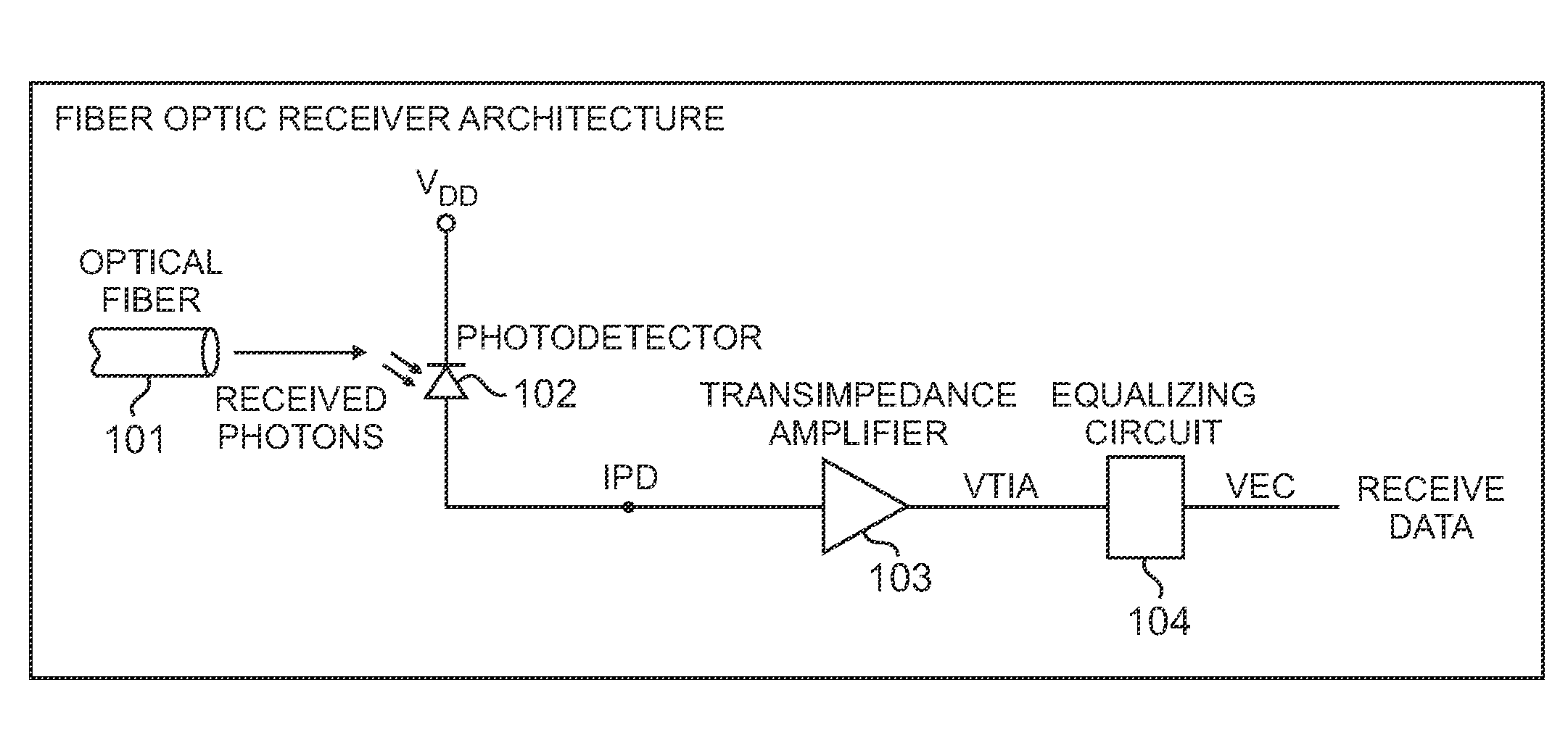
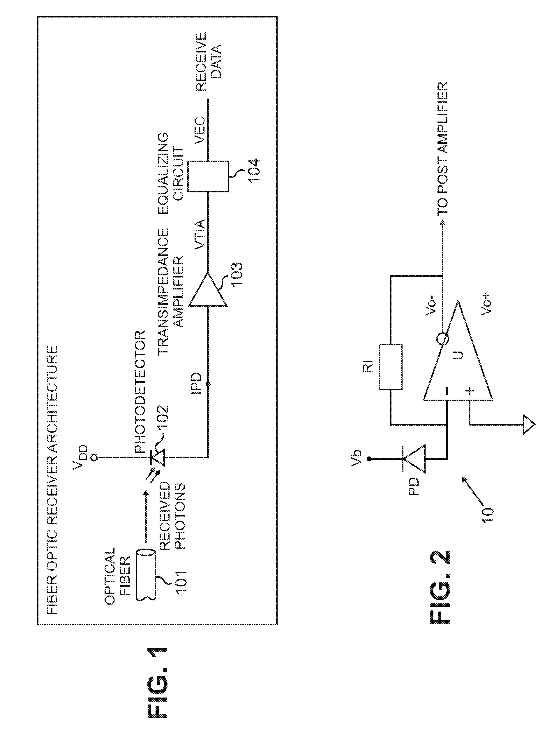
[0022]FIG. 1 is a schematic block diagram of an optical receiver constructed in accordance with the methods and techniques described herein. The light from an optical fiber 101 impinges on a PIN photodiode detector 102, producing a current IPD. Transimpedance amplifier (TIA) 103 converts the relatively small current generated by the photodiode detector into a large signal voltage, VTIA, which is further processed by equalizing circuit 104 to produce a voltage VEC for output to digital circuitry (not shown).

[0023]Two important operating characteristics of the transimpedance amplifier 103 are its transimpedance gain and its bandwidth. A relatively simple illustrative transimpedance amplifier is shown in FIG. 2. The transimpedance amplifier 10 includes a high-speed operational amplifier U having plus (+) and minus (−) inputs and differential outputs labeled Vo− and Vo+. The photodetector PD (e.g., PIN photodiode 102) is connected between a bias voltage source Vb and the minus (−) input...


PUM


Abstract

An optical receiver includes a light receiving element for converting an optical signal to an electrical signal having a first bandwidth and an amplifier for amplifying the electrical signal. The amplifier has a first gain response that yields a second bandwidth that is less than the first bandwidth. The optical receiver also includes an equalizing circuit operationally coupled to the amplifier. The equalizing circuit has a second gain response that compensates for the first gain response of the amplifier so that a substantially constant net gain is imparted by the amplifier and the equalizing circuit to the electrical signal over the first bandwidth.

Description

FIELD OF THE INVENTION[0001]The present invention relates generally to optical receivers, and more particularly to an optical receiver with increased sensitivity that employs a PIN photodiode.BACKGROUND OF THE INVENTION[0002]An optical receiver in which a photodetector serves as a receiver element is one of the key element in an optical fiber transmission network. Optical receivers, in general, function to convert optical signals into electrical signals. A typical optical receiver includes a photodetector connected to the input of an amplifier (e.g., a transimpedance amplifier). The photodetector converts the optical signal it receives into an electric current that is supplied to the amplifier. The amplifier then generates at its output a voltage or current that is proportional to the electric current. The photodetector is typically either an avalanche photodiode (APD) or a PIN (p-intrinsic-n) photodiode. With the recent spread of broadband networks, optical receivers (and optical t...

Claims


Application Information

Patent Timeline
Patent Type & Authority Applications(United States)
IPC IPC(8): H03F3/04H04B10/43
CPCH03F1/48H03F3/08
Inventor BOWLER, DAVID B.CALABRESI, FRANCIS J.LUK, JASON G.
Owner ARRIS ENTERPRISES LLC
Why Eureka
Try Eureka