Protective coat and method for manufacturing thereof

a technology of protective coating and protective layer, which is applied in the direction of vacuum evaporation coating, transportation and packaging, coatings, etc., can solve the problems of difficult to obtain the desired composition, difficulty in obtaining the desired composition, and uncertainty in the quality of the film, so as to prevent the deterioration of film properties and achieve stable el luminescence properties.

Inactive Publication Date: 2009-12-31
HAOTO DAISAKU +1
View PDF19 Cites 26 Cited by
  • Summary
  • Abstract
  • Description
  • Claims
  • Application Information

AI Technical Summary

Benefits of technology

[0015]Therefore, an object of the present invention is to provide an improved protective coat that solves the above-described problems in the conventional art and a method for producing the protective coat.
[0016]Another object of the present invention is to provide, by an improved process, a method for producing a protective coat that enables stable mass production of high quality protective coats that are superior in terms of barrier properties, visible light transparency and uniformity in film quality.
[0017]A further object of the present invention is to provide a protective coat that inhibits the influence of gas emitted from a lower layer such as a substrate, and has a predetermined film thickness and prescribed composition uniformly in the in-plane thereof, and a method for manufacturing thereof.
[0018]A still further object of the present invention is to provide a protective coat and a method for manufacturing thereof, wherein the protective coat prevents deterioration of film properties of an electrode and patterning degradation at a time of electrode formation caused by a gas such as oxygen or moisture emitted from a lower layer, and is useful in obtaining a long-lasting organic EL device or the like in which stable EL luminescence properties and the like are maintained uniformly in the in-plane over a long period after formation of a device.
[0025]According to a protective coat of a first aspect of the present invention described above and a method for manufacturing thereof, stable mass production of a protective coat that is of superior quality with respect to barrier properties, visible light transmittance and film uniformity is enabled when forming a protective coat on a top part of a thin film layered body formed on a top part of a substrate or on a substrate and, for example, when the protective coat is applied as a barrier layer in an organic EL device, it is possible to efficiently inhibit deterioration caused by moisture, oxygen and the like of the organic EL device.
[0032]According to a protective coat of a second aspect of the present invention described above and a method for manufacturing thereof, a protective coat can be provided that inhibits the influence of a gas emitted from a lower layer such as a substrate and that has a prescribed film thickness and a prescribed composition uniformly in the in-plane thereof. It is thus possible to obtain a protective coat that prevents deterioration of film properties of an electrode and patterning degradation at a time of electrode formation caused by a gas such as oxygen or moisture emitted from a lower layer, and which is useful in obtaining a long-lasting organic EL device or the like in which stable EL luminescence properties and the like are maintained uniformly in the in-plane over a long period after formation of a device.

Problems solved by technology

However, in the above US2002093285A1, the barrier properties are discussed in terms of the O / N ratio, and it is an uncertain factor regarding the quality thereof.
However, in studies performed by the present inventors in which we designed for industrial mass production and conducted production using actual equipment when using oxygen in this way, variations in quality arose and it was difficult to obtain the desired composition.
Thus, when using a substrate conveyor-type production apparatus, such as an in-line sputtering apparatus, there are cases where the speed at which substrates are conveyed is very slow.
In addition, this tendency is more noticeable as the size of a substrate increases.

Method used


Image

  • Protective coat and method for manufacturing thereof
  • Protective coat and method for manufacturing thereof

Examples


example 1

(Method of Experiment)

[0082]Polyethersulfone film (manufactured by Sumitomo Bakelite Co., Ltd., SUMILITE FST-5300) (hereunder, referred to as “PES”) was input into a sputtering vacuum chamber, evacuated to 10×10−5 Pa, and maintained in that state for 15 hours to form a barrier film.

[0083]Film formation conditions were as follows:

[0084]Target material: Si3N4 (manufactured by Toshima Seisakusho)

[0085]Ar / N2: 400 sccm / 10 sccm (40:1)

[0086]Film formation pressure: 5 mTorr

[0087]Applied power: 4.3 kW

[0088]Film formation temperature: unheated (approximately 110° C.)

[0089]Film thickness: 3000 A Conveying speed: 58 mm / min

[0090]Overcoat layer: Nippon Steel Chemical Co., Ltd., ph5

[0091]Gas monitor during film formation: Quadrupole mass spectrometer (STADM-2000) manufactured by ULVAC Inc.

[0092]Three conveying carriers were used (first carrier: for ESCA (Si wafer / film); second carrier: measurement of film thickness, transmittance (glass); third carrier: (barrier measurement); all in the same batch...

referencial example 1

[0098]Film formation was conducted in the sane manner as in Example 1, with the exception of employing a film thickness of 500 A, and a conveying speed of 290 mm / min.

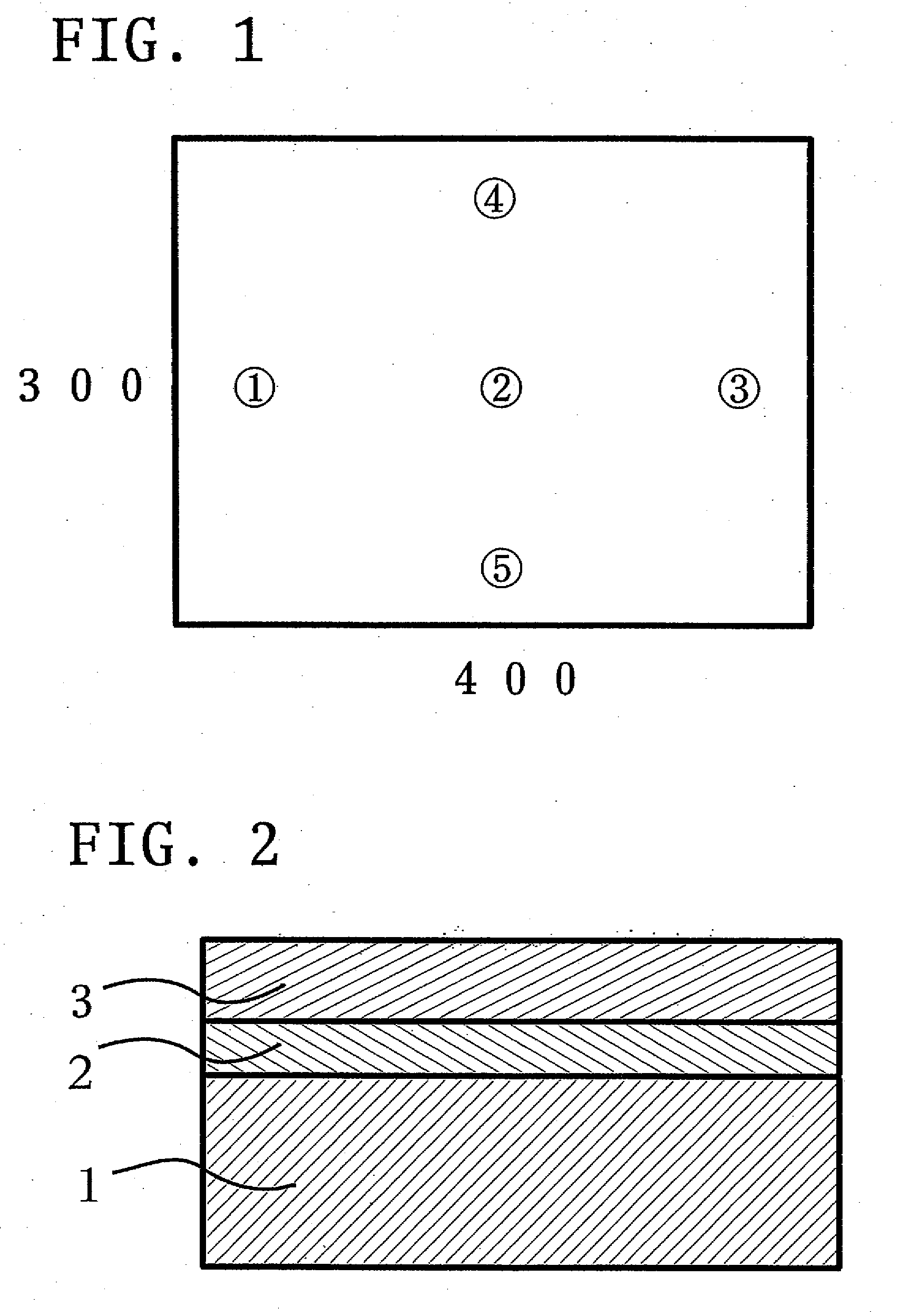
[0099]PES film was used as a substrate, and in the same manner as shown in FIG. 1, evaluation of in-plane composition distribution, transmittance distribution and in-plane barrier distribution was conducted. The results are shown below.

TABLE 2(Measurement results: nitrogen only introduced, 500 A)BarrierBarrierCompositionTransmittanceFilmpropertyproperty(Si / O / N)(%)thickness(WTR)(OTR)1100 / 170 / 297500 A0.550.32100 / 172 / —98500 A0.610.43100 / 175 / —99500 A0.750.554100 / 173 / —98500 A0.620.355100 / 174 / —99500 A0.620.37

[0100]A favorable value was not achieved for barrier properties, and in-plane inconsistencies existed.

[0101]Further, regardless of the introduction of only Ar and nitrogen gas, the results were the sane in that the composition was mostly SiO2 and nitriding did not occur.

referencial example 2

[0108]In order to incorporate a nitrogen component included in the target material into a film under the conditions described in Control 1 (nitrogen / oxygen=8.5), film formation was conducted by raising the RF power (4.5 kW) and increasing the Ar flow ratio (Ar / N / O:400 / 8.5 / 1) so that a transmittance of 85% could be maintained.

TABLE 5(Measurement results: nitrogen and oxygen (mainly nitrogen)introduced, 3000 A)BarrierBarrierCompositionTransmittanceFilmpropertyproperty(Si / O / N)(%)thickness(WTR)(OTR)1100 / 180 / 10833000 A0.690.222100 / 182 / 8853000 A0.750.253100 / 186 / 2893000 A0.810.374100 / 183 / 4873000 A0.730.275100 / 184 / —833000 A0.740.28

[0109]As shown in Table 5, although nitriding was observed, it was of an insufficient amount.


PUM

PropertyMeasurementUnit
distanceaaaaaaaaaa
voltageaaaaaaaaaa
brightnessaaaaaaaaaa

Abstract

A method for producing a protective coat formed on the top surface of a substrate, or on the top surface of a thin film layered body formed on the substrate is disclosed, wherein the protective coat comprises silicon oxynitride in which the atomic ratio of Si / O / N is 100 / X / Y (130≦X+Y≦180, 10≦X≦135, 5≦Y≦150), wherein the protective coat is formed by a sputtering method in which silicon nitride is used as a target material, an inert gas is used as a sputtering gas, and N2 is used as a reactive feed gas. The oxygen component of the obtained protective coat comprising the silicon oxynitride is incorporated into the composition of the protective coat by degradation of moisture that was present in the substrate or the thin film layered body or in the reaction apparatus.

Description

BACKGROUND OF THE INVENTION[0001]1. Technical Field[0002]The present invention relates to a protective coat formed on the top surface of a substrate, or on the top surface of a thin film layered body formed on the substrate and to a method for manufacturing thereof. More specifically, the present invention relates to a method for production that enables mass production at stable high quality of a protective coat such as, for example, a barrier layer formed on an organic layer in which it is difficult to cure an internal part of the film, such as a UV curable resin, which is a so-called “overcoat layer” usable in organic electro luminescent devices and the like, or a barrier layer of a film having a high moisture content, such as polyethersulfone (PES), polyethylene naphthalate (PEN), acrylic UV curable resins and the like used in packaging materials, display devices and the like.[0003]2. Related Art[0004]Liquid crystal display panels are currently widely used as flat display panels,...

Claims


Application Information

Patent Timeline
Patent Type & Authority Applications(United States)
IPC IPC(8): C23C14/14C23C16/22B05D1/36C23C14/34B32B9/00H05B33/04C23C14/06C23C14/32
CPCY10T428/265C23C14/0676H05B33/04
Inventor HAOTO, DAISAKUTANAKA, KENJI
Owner HAOTO DAISAKU
Why Eureka
Try Eureka