Pyrocatalytic coatings for heating devices

Active Publication Date: 2009-12-31
HAIER US APPLIANCE SOLUTIONS INC
View PDF12 Cites 13 Cited by
  • Summary
  • Abstract
  • Description
  • Claims
  • Application Information

AI Technical Summary

Benefits of technology

[0006]In another embodiment, a self-cleaning oven comprises an enameled panel surface defining at least a portion of an oven chamber, the enameled panel surface comprising a layer comprising a metal oxide crystalline catalyst material selected from the group consisting of perovskite crystalline materials, perovskite-like crystalline materials,

Problems solved by technology

Because of the high temperatures used during the self-cleaning mode, a significant amount of thermal insulation about the oven interior is required to prevent damage to delicate electronics.
For example, wiring currently used to operate the oven typically requires special h

Method used


Image

  • Pyrocatalytic coatings for heating devices
  • Pyrocatalytic coatings for heating devices
  • Pyrocatalytic coatings for heating devices

Examples


example 1

[0030]In this example, various catalysts were individually mixed in α-terpineol up to 70wt % using a three-roll mill or a high speed centrifugal mixer to form a homogeneous paste. The catalysts included lanthanum strontium ferrite (LSF), lanthanum strontium cobaltate (LSC), strontium samarium cobaltate (SSC), lanthanum strontium cobalt ferrite (LSCF), cerium oxide (CeO2), and cerium samarium oxide (Ce(Sm)O2). The catalyst paste was painted onto an oven panel section. The coated panel section was dried in an oven at 200° F. (93.3° C.) for 12 hours and then calcined at 925° F. (496.1° C.) in air for 2 hours.

example 2

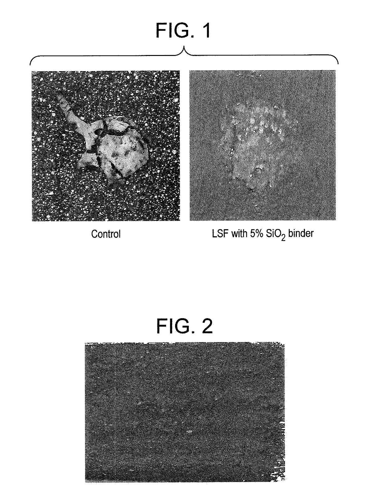
[0031]In this example, the coated panels of example 1 were evaluated to determine the cleanability effectiveness. Approximately 5 g of a processed cheese product commercially available under the trade name CheezWhiz from Kraft foods was used to evaluate the cleanability of the oven panel. CheezWhiz was applied as a food stain to the coated panel using a wooden stick approximately 3 millimeters (mm) in diameter. The diameter of the applied food stain was between 5 mm to 10 mm. The control in the experiment was a standard oven panel cut 1.5″×1.5″ from a GE oven currently used in the market.

[0032]The testing procedure included heating the panel to 350° F. (176.7° C.) for 1 hour at which time the heat was increased to 450° F. (232.2° C.) for 1 hour. The panels were then cooled to room temperature. After staining the oven panel by heating at the elevated temperatures as noted above, all samples had food stain that could be removed only through scrubbing. The samples were then exposed to ...

example 3

[0033]In this example, under-fired panels were used. The oven panel is typically made of two enamel coatings, the ground coat and the top-coat. Top-coat is applied mainly for aesthetics reasons. This coat is responsible for the glaze that is observed on an oven panel. Calcination proceeds after each coat. Hence, oven panels with ground coat and an unfired top-coat were considered for the study. These panels form the top-coat glaze when heated to temperatures greater than 1150° F.

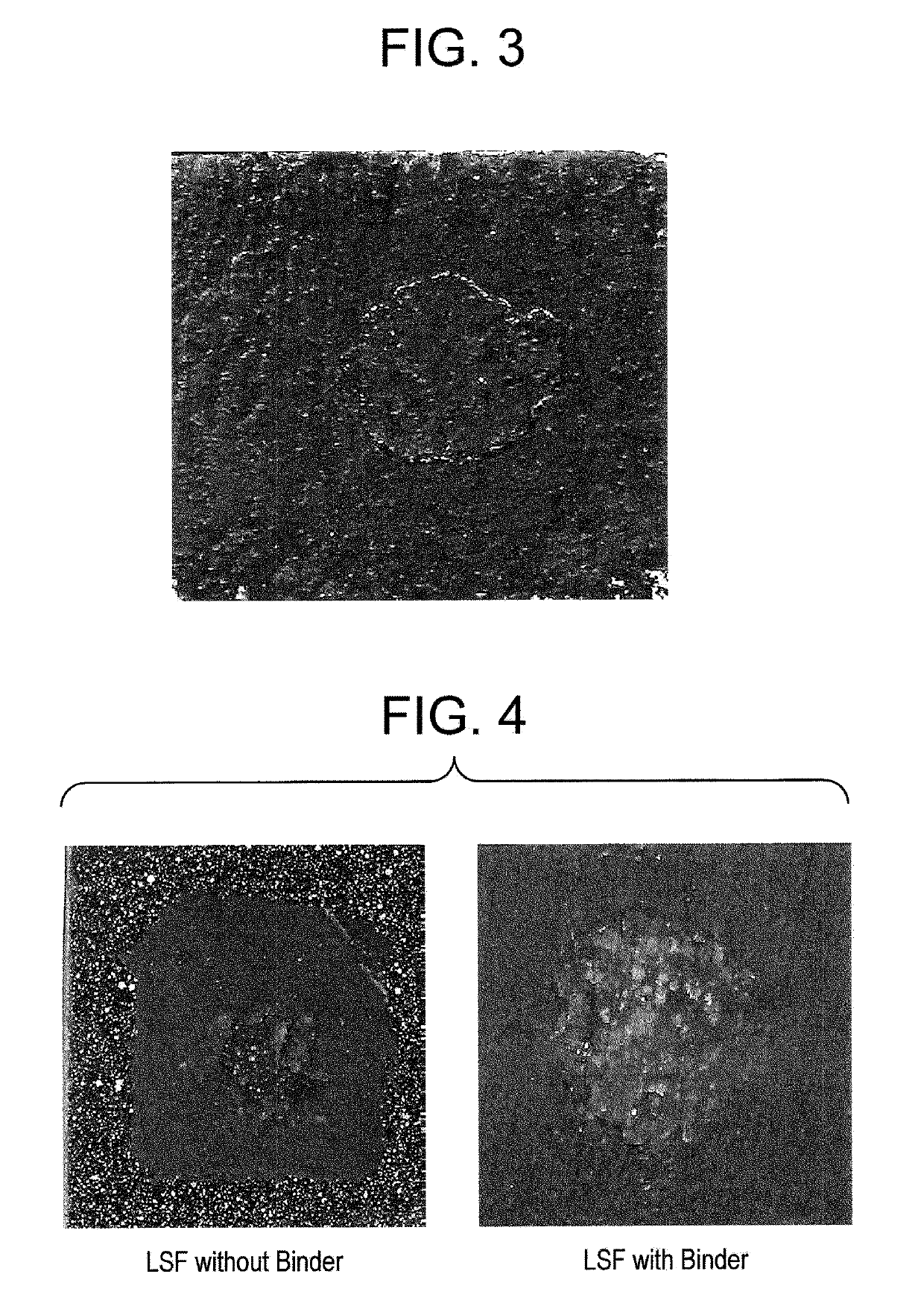
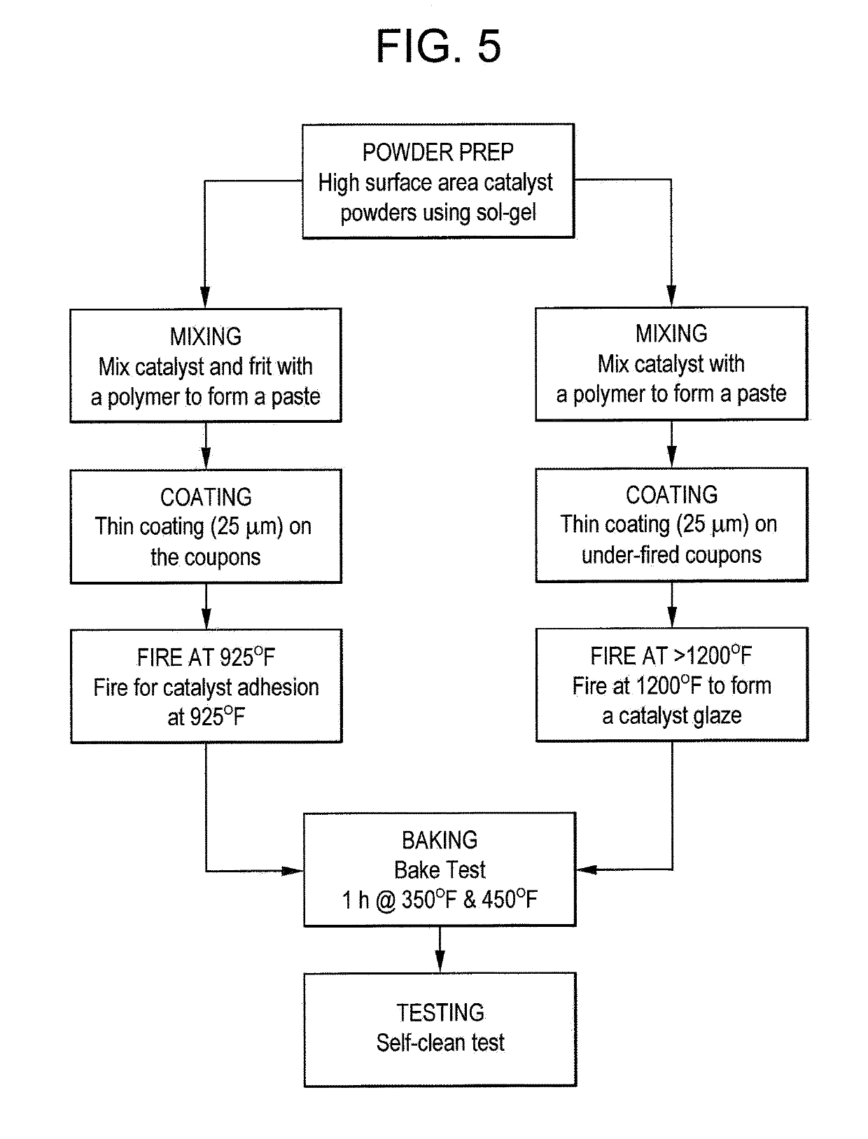
[0034]Of the catalysts described above, LSC and LSF were each individually coated on the under-fired oven panels and calcined at 1200° F. (648.9° C.) for 5 minutes. No SiO2 binder was added. A glossy, rough surface was formed with the catalytic material on top conducive for cleaning. The panels were tested as described earlier. The results for the oven panels coated with LSF and LSC are shown in FIGS. 2 and 3, respectively. Note that after the self-clean cycle as described above there is no imprint of the fo...


PUM

PropertyMeasurementUnit
Temperatureaaaaaaaaaa

Abstract

Heating devices such as self-cleaning ovens include at least one surface comprising metal oxide crystalline catalytic material disposed thereon. The metal oxide crystalline material includes perovskite and perovskite-like materials, pyrochlores, rare earth metal oxides, spinels, and combinations of the foregoing. Also disclosed herein are processes for process for forming a pyrocatalytic coating on a substrate.

Description

BACKGROUND[0001]The present disclosure generally related to pyrocatalytic coatings, and more particularly, pyrocatalytic coatings that include a metal oxide crystalline catalyst material for improved cleanability of heating device surfaces.[0002]Heating devices such as ovens, irons, and cooking surfaces, are often covered with a hard and resistant layer so that foodstuffs, starch, dirt, and the like that can build up on surfaces of these devices during use can be readily cleaned. For example, the walls of an oven are often coated with a smooth enamel coating so that foodstuffs do not permanently adhere to the surface and to permit ashing thereof when the oven is in a self-cleaning mode. Self-cleaning modes for current surface finishes generally require exposing the oven interior to temperatures in excess of 850° F. to completely ash the attached foodstuffs, thereby permitting the end user to wipe away the resulting ash from the surface. Because of the high temperatures used during t...

Claims


Application Information

Patent Timeline
IPC IPC(8): A47J36/02C23C28/04C23C20/08
CPCA47J36/02C23C18/1245C23C18/1216
Inventor VENKATARAMANI, VENKAT SUBRAMANIAMKESHAVAN, HRISHIKESH
Owner HAIER US APPLIANCE SOLUTIONS INC
Why Eureka
Try Eureka