Electroplating method

Inactive Publication Date: 2010-01-07
SES CO LTD +1
View PDF2 Cites 2 Cited by
  • Summary
  • Abstract
  • Description
  • Claims
  • Application Information

AI Technical Summary

Benefits of technology

[0022]By adopting a method such as the one described above, the present invention provides excellent effects as described hereinafter. In other words, when the surface of a metal base is electroplated according to the electroplating method of the present invention, the electroplating solution and the metal base are in contact with each other in an emulsion state because an arrangement is adopted in which electroplating is performed by utilizing the induction codeposition phenomenon using at least one of a carbon dioxide and an inert gas, as well as an electroplating solution containing a metal powder dispersed therein, and a surfactant in a supercritical or a subcritical state. For this reason, the electroplating solution rapidly penetrates into fine holes and grooves, and even a metal base having a complex shape can therefore be effectively electroplated in applications in which fine metal wiring is formed in highly integrated, miniaturized semiconductor circuit elements.
[0023]According to the electroplating method of the present invention, electroplating is performed in a state in which the metal powder is dispersed in the electroplating solution, and the concentration of the metal in the electroplating solution therefore corresponds to a saturated or supersaturated state. Therefore, the dissolution rate of the metal base can be reduced when the metal base is immersed into the electroplating solution, and a uniform film can be obtained by electroplating in a short time by using the induction codeposition phenomenon.
[0024]According to the electroplating method of the present invention, the dissolution rate of the metal base can be reduced when the metal base is immersed into the electroplating solution, for which reason electroplating can be performed in the regular manner even if the metal base is a thin metal film formed on the surface of an insulating film provided on a substrate. In particular, effective use can be made of the method in a Damascene method, dual Damascene method, or other application in which fine wiring is formed in miniaturized semiconductor circuit elements.
[0025]According to the electroplating method of the present invention, because the average particle diameter of the metal powder is set within a range of from 1 μm or greater to 100 μm or less and the solubility of metal powder in the electrolytic solution is high, metal ions can be efficiently fed to the electrolytic solution. In this case, the substrate microstructure to be deposited must be precise to 1 μm or more. An average particle diameter of the metal powder exceeding 100 μm is not preferred because the dissolution rate of the metal powder will be low.
[0026]According to the electroplating method of the present invention, the average particle diameter of the metal powder is set within a range of from 1 nm or greater to less than 1 μm. Therefore, the metal powder can be easily dispersed into the electrolytic solution, not only making aggregation more difficult, but also facilitating electroplating in microstructures having a precision of less than 1 μm.
[0027]The present invention is particularly suited for applications involving formation of fine wiring. The reason is that because a voltage at which the metal base will not dissolve is applied before the metal base is immersed into the electroplating solution, the metal base will not dissolve even if the metal base is immersed into the electroplating solution, and the voltage required for electroplating can be applied once a sufficiently stable state is established after the metal base has been immersed into the electroplating solution.

Problems solved by technology

Our experiments showed, however, that when this metal base was immersed into an electroplating solution to electroplate a similar metal, the metal base was often dissolved even if the metal base was a thick plate, and the plating failed without producing a smooth, normal surface.

Method used


Image

  • Electroplating method
  • Electroplating method
  • Electroplating method

Examples


experimental example 1 through 3

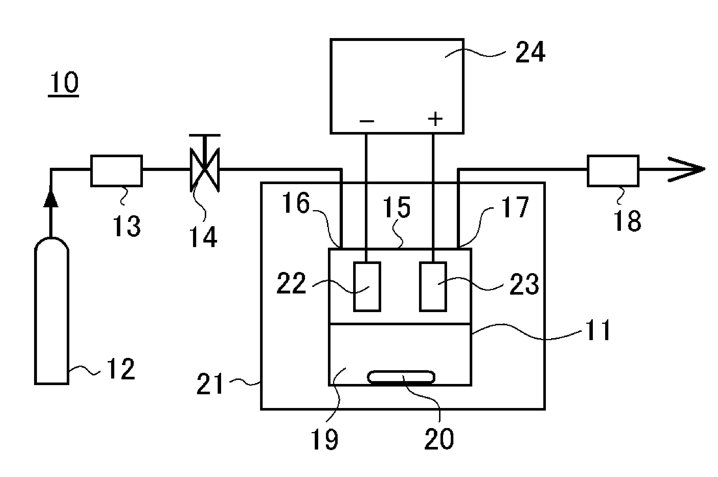
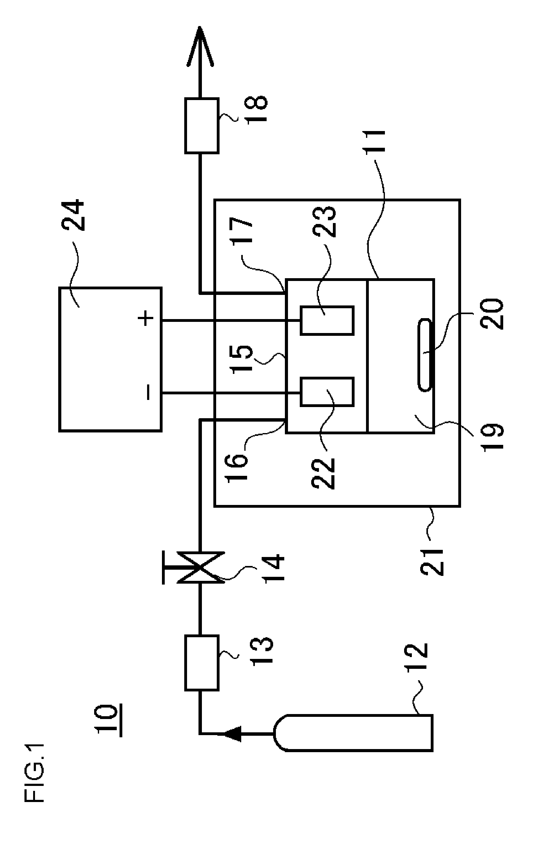
[0055]In Experimental Examples 1 through 3, the solubility of the metal base was investigated when electroplating was conducted in a supercritical state using the high-throw bath. A base obtained by forming a thin copper film having a thickness of 65 nm on a TaN film by sputtering was used as the metal base sample 22. This metal base sample 22 was pretreated by acid pickling and placed together with the counter electrode 23 in the upper part of the electroplating solution 19 in the pressure-resistant plating chamber 11 to as not to be in contact with the electroplating solution 19. The amount of the electroplating solution 19 used was set at 30 mL.

[0056]In this state, the electroplating solution in the pressure-resistant electroplating chamber 11 was heated to a temperature of 40° C.; the electroplating solution 19 was not stirred by the stirrer 20; and the carbon dioxide cylinder 12, the high-pressure pump unit 13, the valve 14, and the pressure adjustment unit 18 were operated to ...

experimental example 1

[0059]Five minutes after the pressure inside the pressure-resistant electroplating chamber 11 became 10 MPa, an electroplating voltage was applied between the metal base sample 22 and the counter electrode 23 from the direct current power source 24.

experimental example 2

[0060]At the same time the pressure inside the pressure-resistant electroplating chamber 11 became 10 MPa, an electroplating voltage was applied between the metal base sample 22 and the counter electrode 23 from the direct current power source 24.


PUM

PropertyMeasurementUnit
Particle diameteraaaaaaaaaa

Abstract

The surface of a metal base is electroplated by utilizing an induction codeposition phenomenon using at least one of carbon dioxide and inert gas, an electroplating liquid containing a metal powder dispersed therein, and a surfactant in a supercritical state or a subcritical state. The concentration of the metal in the electroplating liquid is in a saturated or supersaturated state. Accordingly, the dissolution speed of the metal base can be suppressed, and, at the same time, a plating layer having a smooth surface can be formed in a short time by utilizing an induction codeposition phenomenon. The electroplating method can be applied even when the metal base is formed of a metallic thin film provided on a surface of an insulating film provided on the substrate, or even when the metal is copper, zinc, iron, nickel, or cobalt. The above constitution can provide an electroplating method which, in electroplating on the surface of a metal base, can prevent the dissolution of the metal base to realize normal electroplating even in the case of a very thin metal base.

Description

TECHNICAL FIELD[0001]The present invention relates to an electroplating method for electroplating the surface of a metal base, and particularly relates to an electroplating method in which the dissolution of the metal base that has not yet been electroplated can be prevented, and a uniform film can be obtained by electroplating in a short time using an induction codeposition phenomenon even on a very thin metal base.BACKGROUND ART[0002]In conventional methods for forming a fine metal wiring within a semiconductor element, a thin aluminum film is first formed, for example, on a substrate by sputtering; a photoresist is then applied; a pattern is formed by exposure and development; and a designated wiring is formed by etching. However, such wiring methods have come to be difficult to use with the progress in the increased integration and miniaturization of semiconductor circuit elements, prompting wider use of so-called Damascene methods, in which a wiring groove or hole is formed in ...

Claims


Application Information

Patent Timeline
IPC IPC(8): C25D21/14
CPCC25D3/38C25D15/02C25D5/003H01L21/76877H01L21/2885C25D7/123
Inventor SHIMIZU, TETSUYATAJIMA, HISAYOSHIMIYATA, SEIZOSONE, MASATO
Owner SES CO LTD
Why Eureka
Try Eureka