
Rotation sensor-equipped bearing device for wheel

a technology of rotating sensor and bearing device, which is applied in the direction of mechanical equipment, instruments, transportation and packaging, etc., can solve the problems of increasing space for mounting, inability to detect the direction of rotation, and increasing costs, so as to simplify the construction and increase the reliability of the sensor

Active Publication Date: 2010-01-07
NTN CORP
View PDF2 Cites 15 Cited by
  • Summary
  • Abstract
  • Description
  • Claims
  • Application Information

AI Technical Summary

Benefits of technology

[0015]An object of the present invention is to provide a rotation sensor equipped wheel support bearing assembly, which can detect not only the velocity of rotation but also the direction of rotation, in which a high resolving rotation signal can be utilized in various vehicle controls and which can have a suppressed size for the detection of rotation.
[0017]According to this construction, since the sensor referred to above is of a type capable of detecting change in magnetic field, which results from rotation of the magnetic field generating element, with a sensor having a function of detecting the angle of rotation of the magnetic field generating element, a high resolving and highly precise detection of the angle of rotation can be achieved and not only the velocity of rotation, but also the direction of rotation can be detected. For this reason, a rotation signal so detected can be employed in various vehicle controls. Also, since the magnetic field generating element and the sensor are provided in alignment with the bearing center axis, the sensor employed may be of a type having a reduced size and, hence, even when it is mounted on the wheel support bearing assembly, no increase in size occur, allowing the wheel support bearing assembly as a whole to be suppressed to a reduced size.
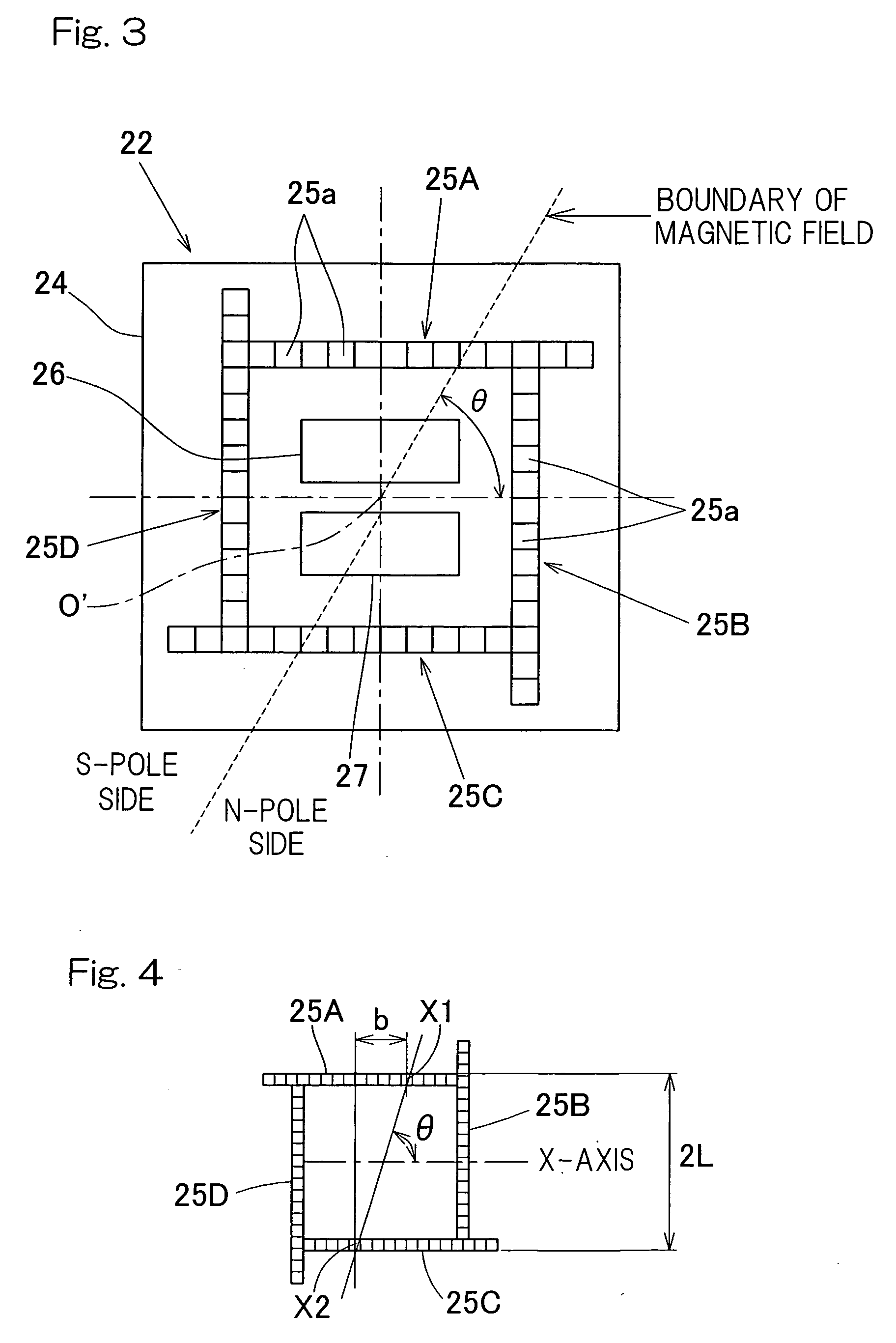
[0019]According to this construction, since the sensor is of a type capable of detecting change in magnetic field, resulting from the rotation of the magnetic field generating element, with the magnetic sensor array and calculating the angle of rotation from respective output of the magnetic sensor elements forming the magnetic sensor array, a further high resolving and highly precise detection of the angle of rotation can be achieved and both of the velocity of rotation and the direction of rotation can also be detected. For this reason, the rotation signal so detected can be utilized in various vehicle controls. Also, since the magnetic field generating element and the sensor are so tailored as to be mounted in alignment with the bearing center axis and the sensor may be of a small size including the magnetic sensor array and circuit component parts, no increase in size will occur even when it is mounted on the wheel support bearing assembly and, therefore, the size of the wheel support bearing assembly as a whole can be suppressed to a minimized size.
[0020]Where the magnetic sensor array is employed, the sensor may be of a type in which the magnetic sensor array, the signal read-out circuit and the angle calculating section are integrated on a semiconductor chip. When the sensor is so designed as to form a sensor IC integrated on the semiconductor chip, the size thereof can be further reduced and, in view of the fact that it is arranged in alignment with the bearing center axis of the wheel support bearing assembly together with the magnetic field generating element and the sensor, the size of the wheel support bearing assembly can be further reduced.
[0023]In the case of this construction, since the entire end of the wheel support bearing assembly is covered by the cover, the use of a sealing member at one axial end of a bearing space, delimited between the outer member and the inner member, where the cover is mounted, can be dispensed with, resulting in simplification of the construction. Also, since the sensor can be protected by the cover, component parts of the sensor will not be exposed to foreign matter and / or muddy saline water and the reliability of the sensor can therefore be increased. Where the outer member is a rotating member, the magnetic field generating element is provided in the cover, and where the inner member is a rotating member, the sensor is fitted to the cover.

Problems solved by technology

Currently mass-produced types of rotation sensors of the magnetic encoder type are merely capable of detecting the velocity of rotation, but not capable of detecting the direction of rotation.
In such case, problems tend to occur that not only does the space for mounting increase, but also the cost increases.
Also, since the magnetic encoder is of a ring shape fitted to an outer periphery or an inner periphery of the rotating side raceway ring, this necessitates an increase of the space for mounting.
With the ABS sensor of the magnetic encoder type discussed above, since the resolving power depends on the number of magnetic poles of the magnetic encoder, it is necessary to minimize the forming pitch of the magnetic poles, but since minimization of the forming pitch of the magnetic poles will result in reduction in magnetic field strength, a large sensor gap can not be secured between the magnetic encoder and the magnetic sensor, thus imposing limitations on manufacturing thereof.
Where the rotation sensor of a resolver type disclosed in the Patent Document 2 quoted above is employed, problems arise in that not only does the size tend to increase for the mounting of the sensor, but also the cost tends to increase.

Method used


Image

  • Rotation sensor-equipped bearing device for wheel
  • Rotation sensor-equipped bearing device for wheel
  • Rotation sensor-equipped bearing device for wheel

Examples


Embodiment Construction

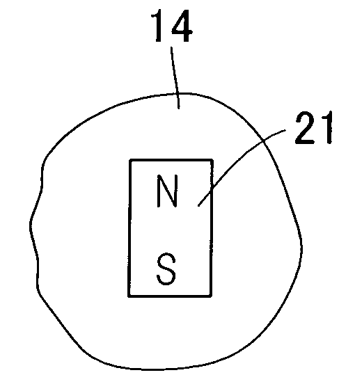
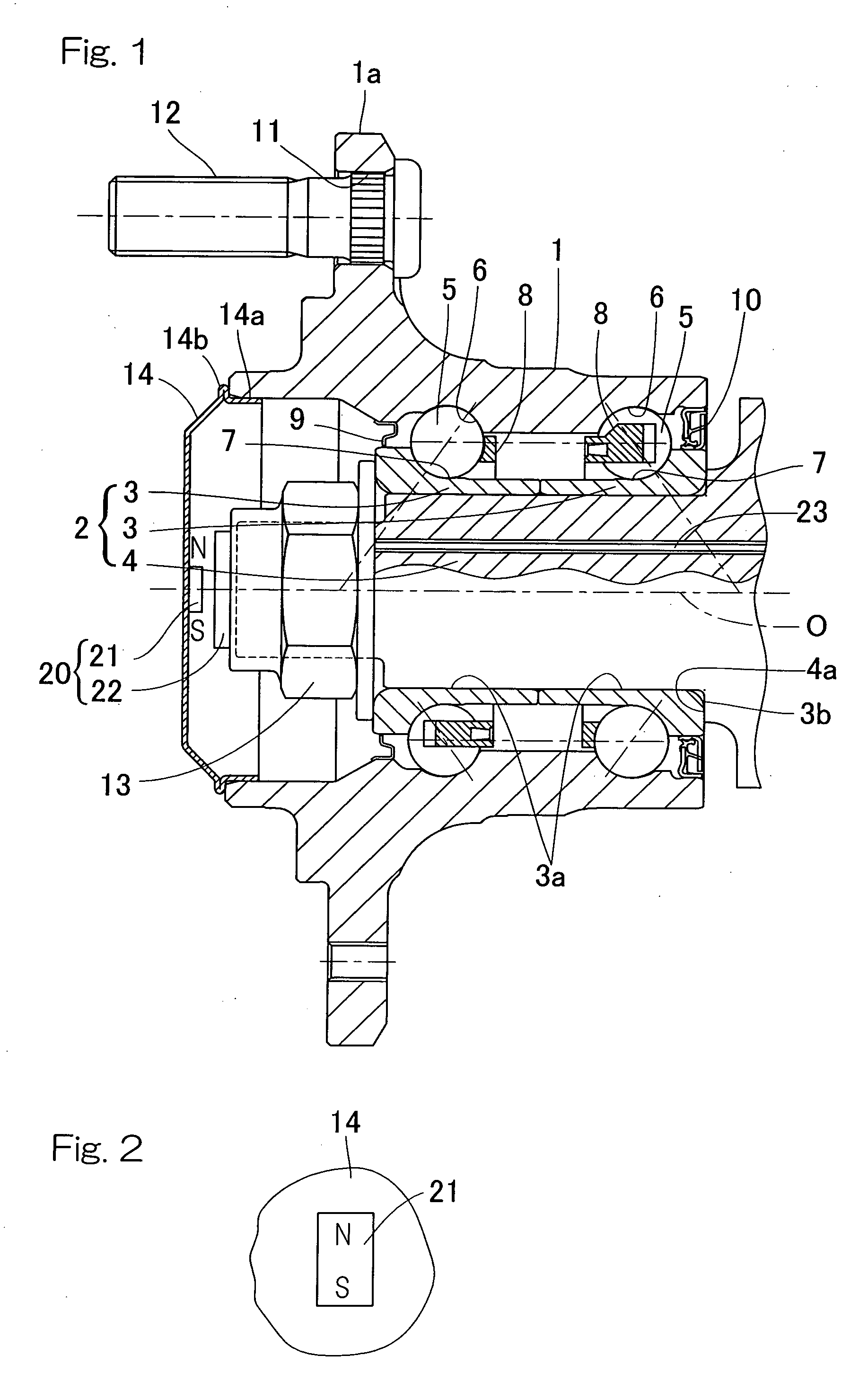
[0032]One preferred embodiment of the present invention will now be described in detail with particular reference to FIGS. 1 to 4. This embodiment is applied to a second generation model of an outer ring rotating type wheel support bearing assembly for the support of a driven vehicle wheel. It is to be noted that in the description that follows, one side of a vehicle body structure laterally away from the longitudinal center thereof in a condition, in which the bearing assembly is mounted on the vehicle body structure, is referred to as “outboard” while the opposite side of the vehicle body structure laterally close towards the longitudinal center thereof in the same condition is referred to as “inboard”.

[0033]The wheel support bearing assembly of the present invention includes an outer member 1 which concurrently serves as a hub axle and has an inner periphery formed with a plurality of rolling surfaces 6 and 6, an inner member 2 having an outer periphery formed with rolling surfac...


PUM


Abstract

A rotation sensor equipped wheel support bearing assembly detects rotational speed and rotational direction, in which a high resolution rotation signal is utilized in various vehicle controls with a suppressed size. The bearing assembly includes a plurality of rows of rolling elements between rolling surfaces in outer and inner members. A magnetic field generating element having anisotropy about a bearing center axis is provided in the outer member in alignment with the axis. The inner member is provided with a sensor for sensing the magnetic field of the magnetic field generating element oriented axially. The sensor detects the angle of rotation of the magnetic field generating element and is in the form of magnetic sensor arrays or elements for detecting the orientation of the magnetic field with a two-dimensional vector sensor to detect rotation of the magnetic field generating element.

Description

BACKGROUND OF THE INVENTION[0001]1. Field of the Invention[0002]The present invention relates to a rotation sensor equipped wheel support bearing assembly for use in, for example, automotive vehicles and, more particularly, to a rotation sensor equipped wheel support bearing assembly suitably employed in a wheel support bearing assembly for the support of a vehicle driven wheel.[0003]2. Description of the Prior Art[0004]As a rotation sensor used in a wheel support bearing unit, a magnetic encoder type for an anti-lock brake system (ABS) has hitherto been employed widely. This is a type which makes use of a ring shaped magnetic encoder and includes a magnetic encoder, fitted to an outer periphery of a rotating side raceway ring, for example, an inner ring, and a magnetic sensor fitted to a stationary side raceway ring or a bearing end cover. (See, for example, the Patent Document 1 listed below.)[0005]Other than the magnetic encoder type, arrangement has been suggested, in which a re...

Claims


Application Information

Patent Timeline
IPC IPC(8): G01B7/30
CPCB60B27/0005B60B27/0084B60B27/0094B60B27/02F16C33/723F16C41/007F16C19/185G01P3/443G01P3/487G01P13/04B60B27/0068F16C2326/02G01D5/145
Inventor MIZUTANI, MASATOSHITAKAHASHI, TORUKIUCHI, MASAHIRO
Owner NTN CORP
Learn More