Methods and apparatus for wavefront manipulations and improved 3-D measurements

a wavefront and wavefront technology, applied in the direction of instruments, using electrical/magnetic means, electric/magnetic measurement arrangements, etc., can solve the problems of poor spatial resolution, poor spatial resolution, and inability to accurately calculate the surface topography. , the effect of poor spatial resolution

Inactive Publication Date: 2010-01-07
ICOS VISION SYST
View PDF10 Cites 36 Cited by
  • Summary
  • Abstract
  • Description
  • Claims
  • Application Information

AI Technical Summary

Benefits of technology

[0020]In addition, the present invention seeks to provide a new apparatus and method for measurement of surface topography in the presence of thin film coatings, which overcomes some of the disadvantages and shortcomings of prior art methods. There exist a number of prior art methods for analyzing a wavefront reflected from or transmitted through an object, such as by interferometry and the wavefront analysis methods described in the above-referenced patent documents. However, the presence of thin films coatings on the surface of the object, adds an additional phase change to the reflected or transmitted wavefront due to multiple reflections. This phase change causes error in calculating the surface topography from which the wavefront was reflected. Knowledge of the thin films coating thicknesses and the refractive indices of the constituent layers, either by prior knowledge or by direct measurement using known methods, enables the added phase change caused by multiple reflections to be calculated by use of known formulas. This additional phase can be eliminated or subtracted from the phase of the reflected or transmitted light in order to correctly calculate the surface topography.
[0021]There is therefore provided, in accordance with a preferred embodiment of the present invention, a phase-measurement system which incorporates the capability of performing accurate measurements also on multi-layered objects, such as in the presence of thin-film coatings. The prior art methods of ellipsometry for performing these operations generally use large illumination spots, which provide poor spatial resolution and poor 2-dimensional imaging capabilities, because of the limited depth of field across the width of such a large illumination spot when large angle of incidence illumination is used. This capability of detection and measurement of multi-layered objects is improved by adding a broadband light source and a filter wheel or a spectrometer to the imaging optical system of the measurement apparatus, such as those described in the above referenced patent documents. Using a filter wheel, the light reflected from the whole field of view is spectrally analyzed independently for each pixel or each segment of the object. Using a spectrometer, the light reflected from one or more selected zones of the object is spectrally analyzed independently for each pixel or segment. The addition of the spectrometer or the filter-wheel enables the measurement of the thicknesses of transparent or semitransparent multi-layers at each segment or each pixel of the object. By combining the phase measurement, the top surface topography is obtained. The thin film coating thicknesses can be calculated accurately, by using the novel spectral analysis methods mentioned above, a predetermined knowledge of the refractive indices and the thicknesses of the layers in the multi-layer stack, and implementing known reflectometry or ellipsometry algorithms. Alternatively and conversely, the refractive indices of the thin films can be calculated accurately, by using the spectral analysis methods mentioned above, predetermined knowledge of the accurate thicknesses of the layers in the multi-layer stack and the known reflectometry or ellipsometry algorithms. Using the known thin film coating thicknesses and the refractive indices at each pixel or each segment of the object, as calculated by the above methods, the phase change due to the presence of the thin film coating can be accurately calculated by known formulae. This phase change, as calculated from the real and complex elements of the refractive index, can be eliminated or subtracted from the measured phase of the reflected or transmitted light in order to attain the surface topography correctly.

Problems solved by technology

However, the presence of thin films coatings on the surface of the object, adds an additional phase change to the reflected or transmitted wavefront due to multiple reflections.
This phase change causes error in calculating the surface topography from which the wavefront was reflected.
The prior art methods of ellipsometry for performing these operations generally use large illumination spots, which provide poor spatial resolution and poor 2-dimensional imaging capabilities, because of the limited depth of field across the width of such a large illumination spot when large angle of incidence illumination is used.

Method used


Image

  • Methods and apparatus for wavefront manipulations and improved 3-D measurements
  • Methods and apparatus for wavefront manipulations and improved 3-D measurements
  • Methods and apparatus for wavefront manipulations and improved 3-D measurements

Examples


Embodiment Construction

[0164]Reference is now made to FIG. 6, which illustrates schematically elements of a first preferred embodiment of the present invention, enabling the detection and measurement of a multi-layer object by means of Ellipsometry, and using methods of phase measurement previously described above. The illumination light source 600 is placed in the optical system in such a way that the surface of the object 602 is illuminated through an imaging system such as a microscope objective 604 with a tilted parallel light beam 606, at a known angle of incidence relative to the normal to the surface of the object. The illuminating light beam 608 is reflected from the object's surface, and is refocused onto the detector 610, which is preferably a pixelated array, by means of the high numerical aperture objective lens 604. By this means, the reflected beam produces an image on the detector, containing information from over a large field of view. Because of the angle of incidence at which the measure...


PUM


Abstract

Methods and apparatus to perform wavefront analysis, including phase and amplitude information, and 3D measurements in optical systems, and in particular those based on analyzing the output of an intermediate plane, such as an image plane, of an optical system. Measurement of surface topography in the presence of thin film coatings, or of the individual layers of a multilayered structure is described. Multi-wavelength analysis in combination with phase and amplitude mapping is utilized. Methods of improving phase and surface topography measurements by wavefront propagation and refocusing, using virtual wavefront propagation based on solutions of Maxwell's equations are described. Reduction of coherence noise in optical imaging systems is achieved by such phase manipulation methods, or by methods utilizing a combination of wideband and coherent sources. The methods are applied to Integrated Circuit inspection, to improve overlay measurement techniques, by improving contrast or by 3-D imaging, in single shot imaging. Data supplied from the esp@cenet database—Worldwide

Description

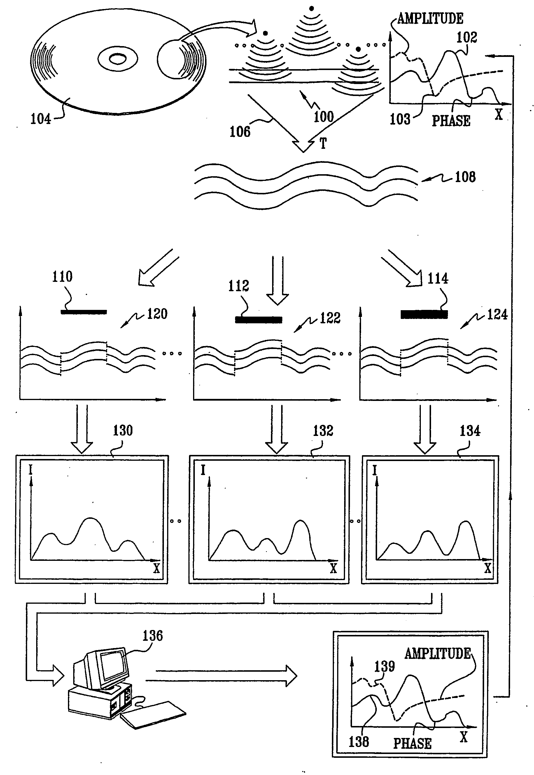
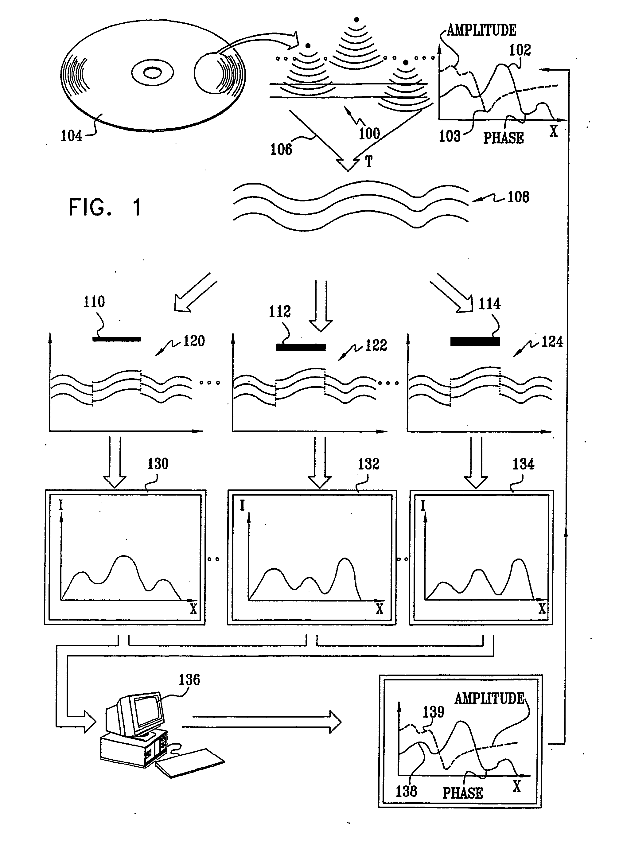
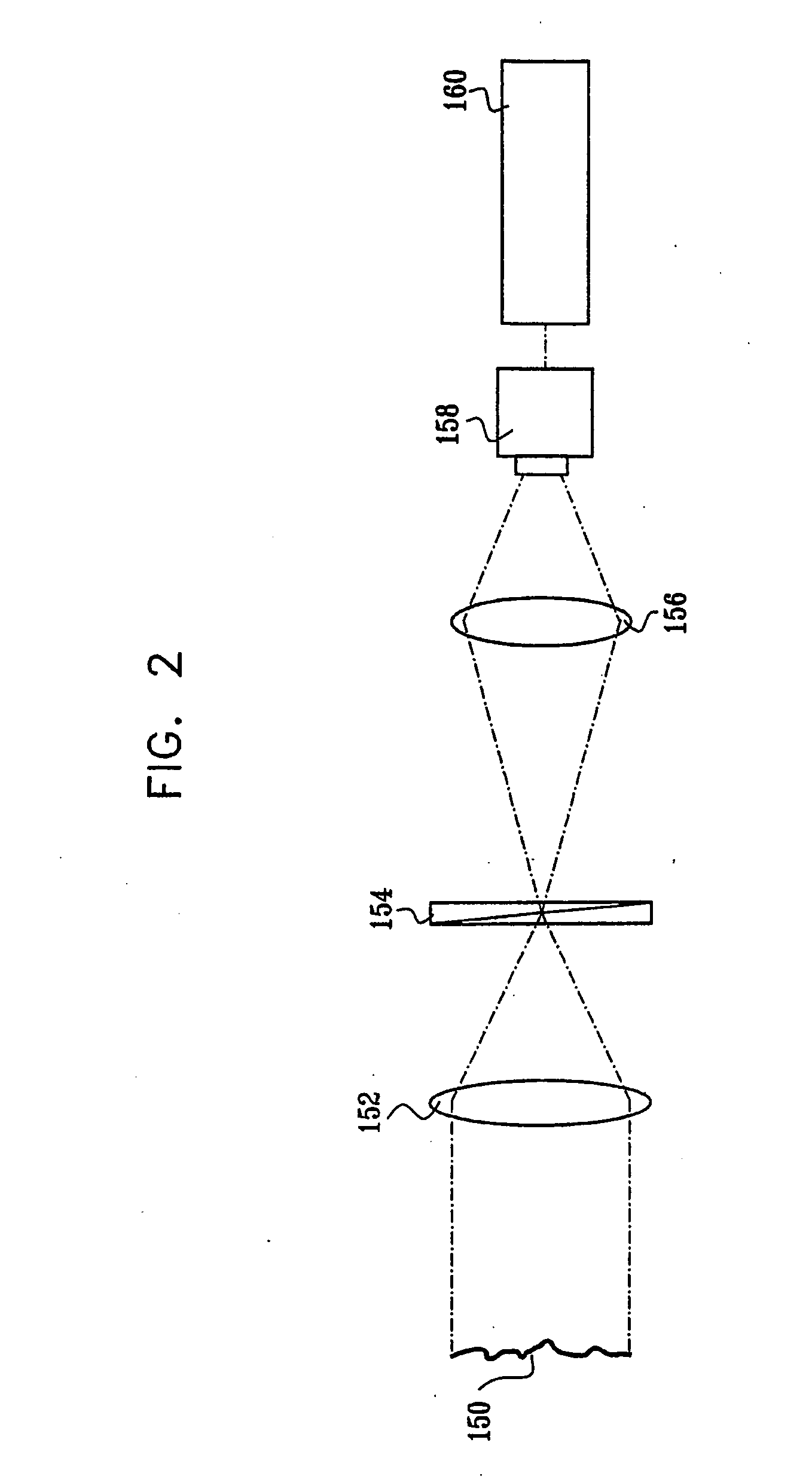
FIELD OF THE INVENTION[0001]The present invention relates to the field of the use of complex optical wavefront measurements in metrologic applications, especially in the fields of the measurement of integrated circuits incorporating thin films, and in image processing applications.BACKGROUND OF THE INVENTION[0002]In co-pending and commonly assigned PCT Application No. PCT / IL / 01 / 00335, published as WO 01 / 77629, U.S. Pat. No. 6,819,435, and PCT Application No. PCT / IL02 / 00833, published as WO 03 / 062743, all of which are incorporated herein by reference, each in its entirety, there are described methodologies and systems for wavefront analysis as well as for surface mapping, phase change analysis, spectral analysis, object inspection, stored data retrieval, three-dimensional imaging and other suitable applications utilizing wavefront analysis.[0003]Some principles of these methods are described in FIGS. 1 and 2. FIG. 1 shows a simplified partially schematic, partially pictorial illustra...

Claims


Application Information

Patent Timeline
Patent Type & Authority Applications(United States)
IPC IPC(8): G06K9/40G01B9/02G01B11/24G01B11/06G06F15/00
CPCG01J9/02G01B9/02G01B9/02087G01B11/24G01B11/0625G01B11/0641G01B11/0675G01B11/06G02B3/00
Inventor ARIELI, YOELWOLFLING, SHAYLANZMANN, EMMANUELFEIGIN, GAVRIELKUZNIZ, TALSABAN, YORAM
Owner ICOS VISION SYST
Why Eureka
Try Eureka